background image

S8VS

Models with Total Run Time Monitor 
(S8VS-

@@@

24B

@@/

S8VS-

@@@

24B

E@

S8VS-06024B 

The accumulated value of the operating time of the Power Supply is 
displayed as the total run time. 

0

 (kh) will be displayed initially after 

purchase and then the display will advance in 

1

-kh steps as the 

operating time accumulates. The S8VS-06024B, however, does not 
have an alarm function (setting, display, or output). 

S8VS-09024B

@@

/S8VS-09024BE

@

S8VS-12024B

@

/S8VS-12024B

E

S8VS-18024B

@

/S8VS-18024BE/ 

S8VS-24024B

@

/S8VS-24024BE/S8VS-48024B 

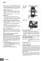
The display will appear when the set value for the total run time has 
been reached. 

Operation mode

Total run time set value reached.

Total run time 

(See note.) 

Total run time 

Note: The alarm (

a02

and the total run

Output 

time will be

voltage 

displayed 
alternately. 

Output 
current 

Peak hold 
current 

The accumulated value of the operating time of the Power Supply is 
displayed as the total run time. 

0

 (kh) will be displayed initially after 

purchase and then the display will advance in 

1

-kh steps as the 

operating time accumulates. When the total run time reaches the 
alarm set value, the alarm (

a02

) and the total run time will be 

displayed alternately and a transistor (total run time output terminal 
(kh)) will output the status externally. 
(Alarm set value reached = OFF, i.e., no continuity at the total run time 
output terminal (kh)) 
The alarm set value can be changed in the setting mode. 
The S8VS-09024BE

@

, S8VS-12024BE, S8VS-18024BE, and S8VS­

24024BE do not have an alarm output. 

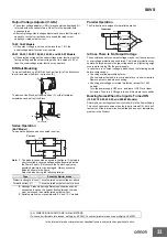
Example: Alarm Displays When a Total Run Time Set Value of 
88 kh Is Reached 

Note: The total run time cannot be reset. To clear the alarm, change 

the alarm set value to a value higher than the value displayed 
for the total run time. 

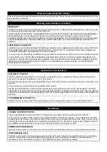
Time Chart 

Total run time 

50 kh 

0 kh 

AC input 

Alarm output 
Set value = 50 kh 
(See note.) 

Setting is possible for the following models only: 
S8VS-09024B

@@

, S8VS-09024BE

@

, S8VS-12024B

@

S8VS-12024BE, S8VS-18024B

@

, S8VS-18024BE, 

S8VS-24024B

@

, S8VS-24024BE, S8VS-48024B 

Note: 1.  The total run time does not include the time that the Power 

Supply is OFF. 

2.  The total run time measures the total time that power is 

being supplied and is not related in any way to deterioration 
in the electrolytic capacitor built into the Power Supply or to 
the effects of the ambient temperature. 

23 

Содержание S8VS 120-W

Страница 1: ... and 480 W models EN 50178 VDE0160 Input conditions DC input is also possible from 80 to 370 VDC BE models only not compliant with EC Directives and other safety standards 15 30 W Models Compact Thin Power Supplies That Mount Just About Anywhere to Contribute to Control Panel Downsizing Compact and thin 22 5 85 96 5 mm W H D Three mounting directions standard horizontal facing horizontal Mounting ...

Страница 2: ... With indication monitor but without alarm output total run time monitor 4 Alarm output None Sinking Emitter COM P Sourcing Collector COM Note No alarm output possible with 60 W models Both sinking and sourcing outputs are available for 480 W models 5 UL Class 2 Output Standards UL 1310 None Does not conform S Conforms 15 W 30 W and 60 W models conform to Class 2 output standards UL 1310 Note The ...

Страница 3: ...VAC allowable 24 V 5 A Sinking S8VS 12024A S8VS 12024A F Sourcing S8VS 12024AP S8VS 12024AP F 180 W range 85 to 264 VAC 7 5 A Sinking S8VS 18024A S8VS 18024A F Sourcing S8VS 18024AP S8VS 18024AP F 240 W 10 A Sinking S8VS 24024A S8VS 24024A F Sourcing S8VS 24024AP S8VS 24024AP F 480 W 20 A Peak current 30 A 200 VAC Sinking sourcing S8VS 48024A S8VS 48024A F Models with Indication Monitor Total Run ...

Страница 4: ...e derating curve in Engineering Data 15 W 30 W Models with no icing or condensation Storage temperature 25 to 65 C Operating ambient humidity 25 to 85 Storage humidity 25 to 90 Dielectric strength 3 0 kVAC for 1 min between all inputs and outputs detection current 20 mA 2 0 kVAC for 1 min between all inputs and PE terminals detection current 20 mA 1 0 kVAC for 1 min between all outputs and PE term...

Страница 5: ...n resistance 10 to 55 Hz 0 375 mm single amplitude for 2 h each in X Y and Z directions 10 to 150 Hz 0 35 mm single amplitude 5 G max for 80 min each in X Y and Z directions Shock resistance 150 m s2 3 times each in X Y and Z directions Output indicator Yes color green EMI Conducted Emissions Models with indication monitor Conforms to EN61204 3 EN55011 Class A and based on FCC Class A Conforms to ...

Страница 6: ...tion 5 No Yes selectable No Yes selectable Undervoltage alarm output terminals No Yes transistor output 30 VDC max 50 mA max 9 No Yes transistor output 30 VDC max 50 mA max 9 Parallel operation No Series operation Yes for up to 2 Power Supplies with external diode Other Operating ambient temperature Refer to the derating curve in Engineering Data 60 W 90 W 120 W 180 W 240 W and 480 W Models with n...

Страница 7: ...inals No Yes transistor output 30 VDC max 50 mA max 9 No Yes transistor output 30 VDC max 50 mA max 9 Parallel operation No Series operation Yes for up to 2 Power Supplies with external diode Other Operating ambient temperature Refer to the derating curve in Engineering Data 60 W 90 W 120 W 180 W 240 W and 480 W Models with no icing or condensation Storage temperature 25 to 65 C Operating ambient ...

Страница 8: ...r V INPUT DC OUTPUT V S8VS 06024A 60 W S8VS 06024B 60 W AC L INPUT Noise filter AC N Voltage detection circuit Photocoupler Rectifier smoothing circuit Fuse Rectifier smoothing circuit Inrush current Rectifier smoothing protection circuit Drive control circuit 3 15 A Overcurrent Current detection circuit circuit Arithmetic operation circuit Display circuit Switch Overvoltage detection circuit circ...

Страница 9: ...otocoupler Alarm DC Low Yrs kh Common Inrush current protection circuit S8VS 09024A F 90 W S8VS 09024B F 90 W S8VS 09024AS 90 W S8VS 09024BS 90 W S8VS 09024AP F 90 W S8VS 09024BP F 90 W S8VS 09024APS 90 W S8VS 09024BPS 90 W S8VS 09024BE 90 W S8VS 09024BES 90 W Fuse 8 0 A AC L INPUT AC N Switch Rectifier V V Voltage detection circuit Photocoupler Photocoupler Rectifier smoothing circuit Rectifier s...

Страница 10: ...cuit Arithmetic operation circuit Display circuit Switch Photocoupler Alarm DC Low Yrs kh Common Harmonic current suppression Smooth ing circuit S8VS 12024B 120 W S8VS 12024A F 120 W S8VS 12024B F 120 W Sinking type S8VS 12024A F S8VS 12024B F Sourcing type S8VS 12024AP F S8VS 12024BP F Noise filter AC L INPUT AC N V Yrs kh Common V DC OUTPUT Fuse 5 0 A Display circuit Switch Rectifier Inrush curr...

Страница 11: ...nt detection circuit S8VS 18024B 180 W S8VS 18024A 180 W Sinking type S8VS 18024A S8VS 18024B Sourcing type S8VS 18024AP S8VS 18024BP Alarm DC Low Yrs kh Common S8VS 18024A F 180 W S8VS 18024B F 180 W Sinking type S8VS 18024A F S8VS 18024B F Sourcing type S8VS 18024AP F S8VS 18024BP F S8VS 18024AP F 180 W S8VS 18024BP F 180 W S8VS 18024BE 180 W Fuse 6 3 A AC L V DC OUTPUT INPUT Type with no alarm ...

Страница 12: ...hing circuit Arithmetic operation circuit Display circuit Switch Photocoupler Alarm DC Low Yrs kh Common Rectifier Harmonic current suppression Smooth ing circuit S8VS 24024A F 240 W S8VS 24024B F 240 W Sinking type S8VS 24024A F S8VS 24024B F Sourcing type S8VS 24024AP F S8VS 24024BP F Noise filter V Yrs kh Common V V V DC OUTPUT Fuse 8 0 A Display circuit Switch Inrush current protection circuit...

Страница 13: ...24 480 W S8VS 48024A 480 W S8VS 48024B 480 W Drive circuit Auxiliary power supply circuit Control circuit V V V V DC OUTPUT Fuse 12A AC L INPUT AC N DC LOW Yrs kh Sinking Sourcing S8VS 48024A B V V Noise filter Rectifier Rectifier smoothing circuit Rectifier smoothing circuit Photocoupler Display circuit Switch Harmonic current suppression Smoothing circuit Inrush current protection circuit Voltag...

Страница 14: ... 1 No Name Function 1 AC Input terminals L N 2 2 Protective Earth terminal PE 3 DC Output terminals V V 4 Output indicator DC ON Green 4 5 5 6 Output voltage adjuster V ADJ 6 3 120 100 1 120 100 1 80 1 80 1 60 2 40 60 2 40 3 20 20 0 20 10 0 10 20 30 40 50 60 70 80 0 Ambient temperature C 20 10 0 10 20 30 40 50 60 70 80 1 Standard mounting Ambient temperature C 2 Face up mounting Horizontal mountin...

Страница 15: ...d protection is activated if the output current rises above 105 of the rated current When the output current returns within the rated range overload protection is automatically cleared 15 W Models 30 W Models The values shown in the above diagram is for reference only Note 1 Do not turn ON the power again until the cause of the overvoltage has been removed 2 The overvoltage protection of the S8VS ...

Страница 16: ...icated parameter or reset the peak hold current value Use the Up Key to change to the setting mode or to increase the set value Use the Down Key to change to the setting mode or to decrease the set value Output when a drop is detected in the output voltage voltage drop transistor OFF Output when the set value for maintenance is reached transistor OFF Output when the set value for total run time is...

Страница 17: ...ent value 16 4 15 5 Use the Up Key to change to the 9 Up Key 3 setting mode or to increase the set 3 value 14 13 12 11 Note The illustration shows the S8VS 48024A model Use the Down Key to change to the 10 Down Key 3 setting mode or to decrease the set value The terminal arrangement is the same for models with screwless terminal blocks and standard models Undervoltage output terminal 11 DC Low Emi...

Страница 18: ...d Peak hold current Maximum current output by Power Supply is recorded and displayed Total run time monitor Note 1 The peak hold current starts measuring the current 3 seconds after the Power Supply is started Inrush current is thus not measured 2 For the factory setting the output voltage will be displayed when the power supply is first turned ON Thereafter the output voltage will be indicated in...

Страница 19: ...nt Maintenance forecast monitor Note 1 When the voltage is restored to the set value or higher and the Key is pressed at the a01 display to return to the output current display the a01 alarm will be cleared and the normal output display will return 2 The above displays are for models with a maintenance forecast monitor S8VS 24A Multiple Alarms When two or more different alarms occur at the same ti...

Страница 20: ...rvoltage output terminal DC LOW turns OFF Maintenance forecast output terminal Yrs turns OFF or total run time output terminal kh turns OFF Turn the AC input OFF then ON again If the Product is not reset contact the dealer No change e04 e05 Hardware error S8VS 48024A B only Undervoltage output terminal DC LOW turns OFF Maintenance forecast output terminal Yrs turns OFF or total run time output ter...

Страница 21: ...etting L which can be set arbitrarily from 0 0 to 5 0 years in 0 5 year steps is set to a value larger than two years the indication automatically changes to a value L 0 5 after the remaining time to maintenance is reduced to the set years and an alarm a02 and the remaining time are indicated alternately If the setting is less than 2 0 years the indication changes to a value 1 5 after the remainin...

Страница 22: ...ly the speed follows Rule of Two for every 10 C for every 10 C increase in temperature the rate of degradation doubles according to Arrhenius s equation The S8VS 24A monitors the temperature inside the power supply and calculates the amount of deterioration according to the running hours and inside temperature Judging by this amount of deterioration the power supply will give the alarm indication ...

Страница 23: ...When the total run time reaches the alarm set value the alarm a02 and the total run time will be displayed alternately and a transistor total run time output terminal kh will output the status externally Alarm set value reached OFF i e no continuity at the total run time output terminal kh The alarm set value can be changed in the setting mode The S8VS 09024BE S8VS 12024BE S8VS 18024BE and S8VS 24...

Страница 24: ...ed to an excessive voltage even if the feedback circuit in the Power Supply fails If an excessive voltage that is approximately 130 of the rated voltage but approximately 110 of the rated voltage for the S8VS 09024 S or more is output the output voltage is shut OFF Reset the input power by turning it OFF for at least three minutes and then turning it back ON again Mounting Output voltage V Upper U...

Страница 25: ... the S8VS 09024A Drops to the Set Value 19 0 V or Lower In the case that the output voltage drops below the set value 19 0 V and an alarm is issued Note 1 Operation begins after about three seconds since the AC power is supplied 2 The alarm is not indicated in the setting mode 3 Press the Mode Key 8 after the output voltage is restored to reset alarm indication 4 The undervoltage alarm function ma...

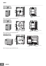
Страница 26: ...on is the S8VS 06024A model S8VS 09024 90 W S8VS 09024S 90 W S8VS 12024 120 W S8VS 09024A 90 W S8VS 09024A S 90 W S8VS 12024A 120 W S8VS 09024B 90 W S8VS 09024B S 90 W S8VS 12024B 120 W S8VS 09024BE 90 W S8VS 09024BES 90 W S8VS 12024BE 120 W Five M4 terminal screws with square washers 10 8 110 5 10 35 4 94 115 1 50 4 5 121 3 Rail stopper Sliding 15 max Screwless block 2 5 mm pitches Note The illus...

Страница 27: ...Screwless block 2 5 mm pitches Note The illustration shows the S8VS 48024A model Power Supplies with Screwless Terminal Blocks S8VS 06024 F 60 W 10 2 S8VS 06024A F 60 W 97 1 10 S8VS 06024B F 60 W 35 4 77 4 95 1 40 107 3 4 5 Sliding 15 max Rail stopper Note The illustration shows the S8VS 06024 F model S8VS 09024 F 90 W S8VS 09024S F 90 W S8VS 12024 F 120 W S8VS 09024A F 90 W S8VS 09024A S F 90 W S...

Страница 28: ... 24024 F 240 W 6 7 100 S8VS 24024A F 240 W 117 6 10 S8VS 24024B F 240 W S8VS 24024BE F 240 W 35 4 97 3 115 1 10 124 3 4 5 Sliding 15 max 50 Rail stopper Rail stopper Note The illustration shows the S8VS 24024 F model S8VS 48024 F 480 W S8VS 48024A F 480 W 127 2 S8VS 48024B F 480 W 122 9 150 35 4 96 3 115 10 4 5 Sliding 15 max 70 Rail stopper Rail stopper Note The illustration shows the S8VS 48024 ...

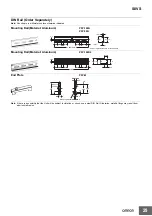
Страница 29: ...alues in parentheses are for the PFP 50N Mounting Rail Material Aluminum PFP 100N2 16 4 5 15 25 25 10 10 1 000 25 25 15 35 0 3 27 24 29 2 1 1 5 End Plate PFP M 1 3 4 8 35 5 35 5 1 8 1 8 10 6 2 1 M4 8 pan head screw 11 5 10 M4 spring washer 50 Note If there is a possibility that the Unit will be subject to vibration or shock use a steel DIN Rail Otherwise metallic filings may result from aluminum a...

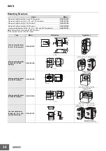
Страница 30: ...cket For 15 30 W models S82Y VS30P 22 5 15 93 6 15 t 0 8 Left side mounting Right side mounting 4 5 dia 0 1 60 0 1 Side mounting Bracket 80 For 60 90 120 W S82Y VS10S models 35 55 0 1 13 64 t 2 0 Left side mounting 4 5 dia 0 1 Side mounting Bracket 80 60 0 1 For 180 W models S82Y VS15S 47 5 55 0 1 89 78 t 2 0 Right side mounting also possible Left side mounting 4 5 dia 0 1 80 60 0 1 Side mounting ...

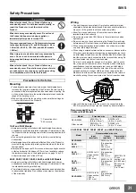
Страница 31: ...s may occasionally deteriorate and be broken due to adverse heat radiation Do not loosen the screw on the side face of the main body Wiring Connect the ground completely A protective earthing terminal stipulated in safety standards is used Electric shock or malfunction may occur if the ground is not connected completely Minor fire may possibly occur Ensure that input and output terminals are wired...

Страница 32: ...dically check if the maintenance forecast monitor output Yrs or total run time monitor output kh is correctly functioning by the following procedure 1 Select the operation mode 2 Check that the output Yrs kh is turned ON with continuity 3 In the operation mode press and hold the Down Key D 10 and the Mode Key M 8 simultaneously for at least three seconds The main display 6 changes to a02 An inacti...

Страница 33: ...orward current IF Twice the rated output current or above 2 Although Products having different specifications can be connected in series the current flowing through the load must not exceed the smaller rated output current 3 Serial operation is not possible with 5 V and 12 V models Parallel Operation The Product is not designed for parallel operation Incorrect V V V V AC L AC N AC L AC N In Case T...

Страница 34: ...MEMO 34 ...

Страница 35: ...combination of products in the customer s application or use of the products Take all necessary steps to determine the suitability of the product for the systems machines and equipment with which it will be used Know and observe all prohibitions of use applicable to this product NEVER USE THE PRODUCTS FOR AN APPLICATION INVOLVING SERIOUS RISK TO LIFE OR PROPERTY WITHOUT ENSURING THAT THE SYSTEM AS...

Страница 36: ... U S A Tel 1 847 843 7900 Fax 1 847 843 7787 Regional Headquarters OMRON EUROPE B V Wegalaan 67 69 2132 JD Hoofddorp The Netherlands Tel 31 2356 81 300 Fax 31 2356 81 388 Contact www ia omron com Tokyo JAPAN OMRON ASIA PACIFIC PTE LTD No 438A Alexandra Road 05 05 08 Lobby 2 Alexandra Technopark Singapore 119967 Tel 65 6835 3011 Fax 65 6835 2711 OMRON CHINA CO LTD Room 2211 Bank of China Tower 200 ...

Отзывы: