Using NQ-Designer
Section 4-2
29
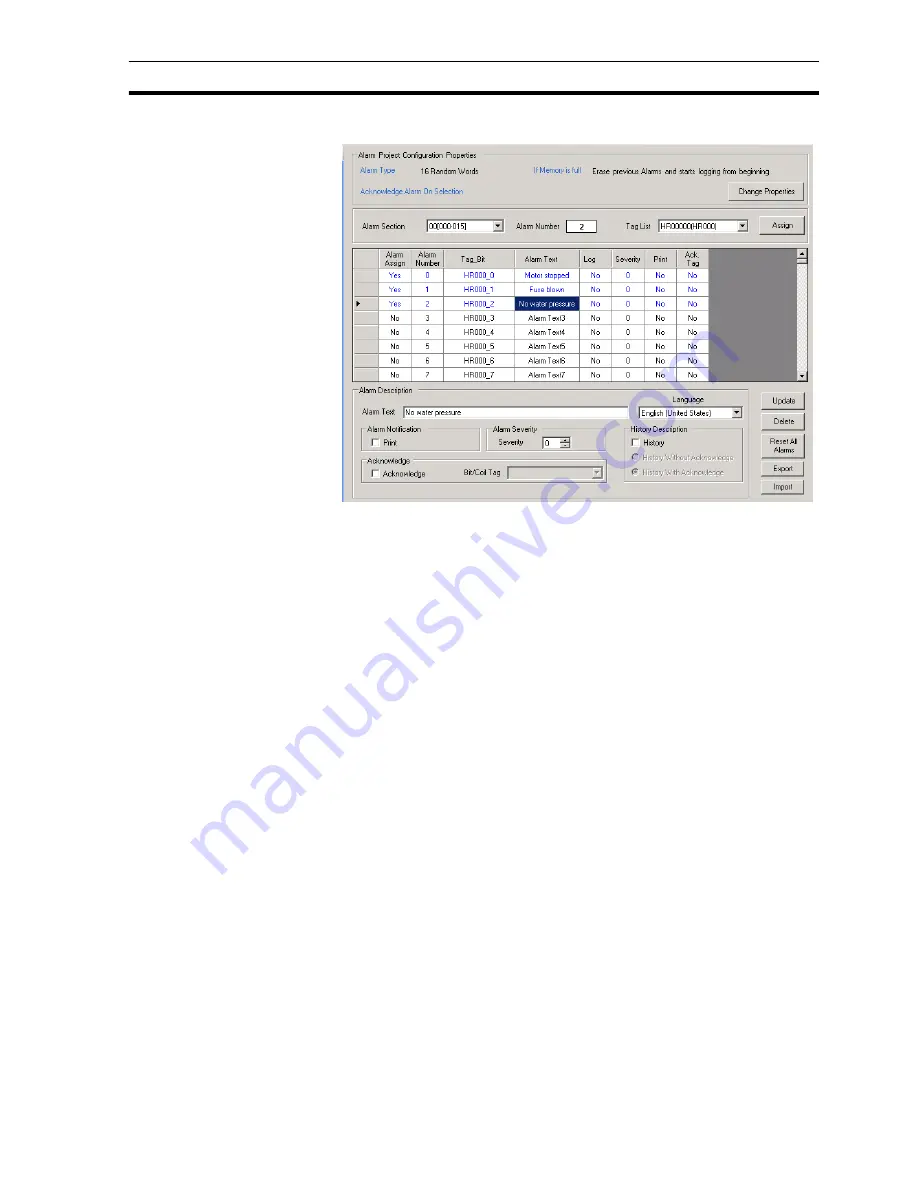
Attached image shows a screenshot of the alarm screen.
Figure 4.4: Alarm project configuration properties
Above image shows the window that is shown when opening the alarm folder.
From top to bottom you see:
• Alarm type: 16 random words (this is the selection made in the alarms tab
starting the project)
• Also action, If alarm memory is full, this is also selected in the alarm tab,
and the action that is performed.
• Acknowledge alarms on selection, this means that for each alarm an
acknowledge bit must be selected.
If any of the selections made above is incorrect, press button
Change
properties
.
Note that this will erase any alarm assignments already created.
For assigning the alarm register that will be used to trigger alarms a tag has to
be created in tag list.
Example:
HR000 is the alarm register used in the PLC program. Create a tag with
HR000 in your tag list. Select this created tag and assign the alarm register.
Upon assigning you will see that the first 16 lines are now identified as alarms.
Bit HR000.00 as alarm 0 (Motor stopped), bit HR000.01 as alarm 1 (Fuse
blown), etc.
Clicking on alarm 0 first line allows you to enter the alarm text, acknowledge
(Y/N) and which bit should be used to perform ACK, severity, real time alarm
or Historical alarm.
When all of these settings are made you click button ACCEPT. You see now
all text turns blue and alarm sign has changed to YES.
With this method you can assign all alarms used in your project.
Содержание NQ HMI
Страница 1: ...NQ Series HMI GETTING STARTED GUIDE Cat No V07 EN 01 NQ3 TQ0 B NQ3 MQ0 B NQ5 SQ0 B NQ5 MQ0 B...
Страница 2: ......
Страница 6: ......
Страница 14: ...Conformance to EC Directives Section 1 7 xiii...
Страница 20: ...Specifications per model Section 2 4 6...
Страница 78: ...Debugging Section 6 2 64...
Страница 88: ...NQ Series diagnostics Section 7 4 74...
Страница 144: ...130...


