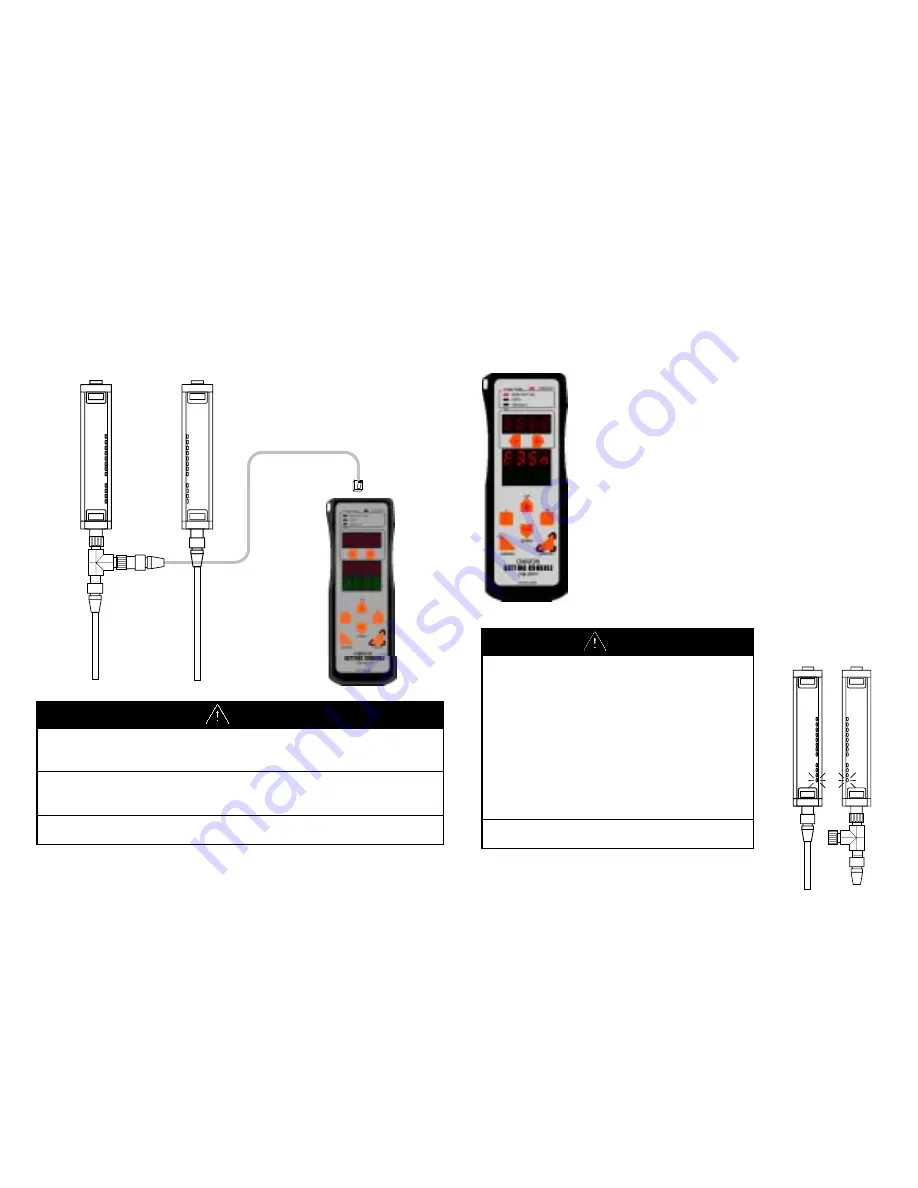
manualshive.com logo in svg
background image

- 9 - 

4.3 Connecting 

F39-MC 

 
Insert M12 connector of the cable into Branching connector and the 
other end into the F39-MC11. 


CAUTION 

Do not connect 2 or more F39-MC to one pair of sensor. Normal 
operation cannot be achieved. Also, combined use of F39-MC and 
F3ZP, area scanner controller, is not allowed.


When F39-MC is not in use, the cable and F39-MC must be removed 
and Branching connector must be covered with connector cap (Model 
XS2Z-12).


When connecting or disconnecting the F39-MC, be sure that the power 
is OFF.


- 10 - 

5 POWER 

ON 

 
Power supply of F39-MC is shared with that of the sensor.   
The F39-MC turns ON with the power supply of the sensor. 
 

When the F39-MC power is ON, it confirms its 
connection to sensor. When connection is succeeded, 
it displays as follows; 

Communication connecting indicator is lit. 

Displays F39-MC’s model and version in mode   

display (for 1 second) 

Displays connected sensor model in mode display, 

(for 1 second) 

 
(Figure shown left represents when connected to 
Model F3SN-A.) 


CAUTION 

When F39-MC power is ON, the state of sensor 
becomes as follows. 

• 

The safety output of F3SN and F3SH is OFF. 
Also, indicators located at bottom (see fig. on 
right) are flashing. 

• 

The output of F3ZN is OFF only during 
sending data to F3ZN. During non-access 
time, normal operation can be conducted 
except that the response time increases by 
1ms. 

 
Do not disconnect the F39-MC during power 
ON-state. Malfunction may result.


Содержание F39-MC11

Страница 1: ...m date of sale by OMRON OMRON MAKES NO WARRANTY OR REPRESENTATION EXPRESS OR IMPLIED REGARDING NON INFRINGEMENT MERCHANTABILITY OR FITNESS FOR PARTICULAR PURPOSE OF THE PRODUCTS ANY BUYER OR USER ACKN...

Страница 2: ...EN DESIGNED TO ADDRESS THE RISKS AND THAT THE OMRON PRODUCTS ARE PROPERLY RATED AND INSTALLED FOR THE INTENDED USE WITHIN THE OVERALL EQUIPMENT OR SYSTEM PROGRAMMABLE PRODUCTS OMRON shall not be respo...

Страница 3: ...volves a change of the safety distance Always recalculate and re measure the safety distance to confirm that it meets the applicable standards after the change Failure to do so may cause the machine t...

Страница 4: ...nal indicator output 27 8 6 External device monitoring 30 8 7 Start interlock 31 8 8 Restart interlock 32 8 9 Threshold adjustment 33 8 10 Setting initialization 34 8 11 ID setting 35 8 12 Threshold t...

Страница 5: ...load Bank lock Protect Setting lock Change password Setting limitation Accessible For the sensor having the specific serial number this function is unavailable Refer to 1 2 Available function and Sens...

Страница 6: ...02 or aaaabcc aaaa can be any numeric characters b can be any alphanumeric characters cc is greater than 03 The functional group B The following serial numbers correspond to the functional group B Ser...

Страница 7: ...ector when F39 MC is not in use Brief description of Operation keys 6 CANCEL ENTER DOWN R L UP MONITOR SET COPY PROTECT FUNCTION 3 1 Communication connection indicator CONNECT This indicator will ligh...

Страница 8: ...connector Emitter Receiver Emitter Receiver 8 4 2 Diagram for Wiring of Branching Connector Front View Pin No Signal 1 24 V 24VDC 2 RS 485 A 3 0V 4 RS 485 B CAUTION The F39 MC receives its power from...

Страница 9: ...with the power supply of the sensor When the F39 MC power is ON it confirms its connection to sensor When connection is succeeded it displays as follows Communication connecting indicator is lit Displ...

Страница 10: ...e item of respective function Monitor Set Section8 page14 Copy Section9 page41 Protect Section10 page45 DOWN UP MONITOR SET COPY PROTECT FUNCTION MONITOR SET COPY PROTECT FUNCTION MONITOR SET COPY PRO...

Страница 11: ...the setting can only be done under observance of laws standards which are related to safe operation of the product This function enables the monitoring of current set values and functions of the senso...

Страница 12: ...a power supply should be dropped a sensor may not carry out normal operation 16 8 1 Fixed blanking F3SN F3ZN CAUTION In order prevent access to a dangerous area fixed barrier guards must be placed in...

Страница 13: ...clear Note Models produced before April 2002 can not use setting of Surveillance mode Sensors which has specific serial number also can not use the setting If the surveillance mode is set to above mo...

Страница 14: ...n valid Place an object where you want to be blanked Select 2 tch Ent Beams select Send setting to sensor Setting completed good displayed ONE POINT After setting has completed you can confirm the bla...

Страница 15: ...OFF when 2 or more beams are blocked 22 CAUTION Use of floating blanking function involves a change of the safety distance Always recalculate and re measure the safety distance to confirm that it meet...

Страница 16: ...alid OFF Invalid ON Valid OFF Invalid GOOD ERR 24 8 3 Auxiliary output F3SN F3SH This is a non safety related output used to display a status This output cannot be used for the purpose of safety This...

Страница 17: ...cked beams Err is displayed 3 AUX 1 D ON 2 L ON 3 L DG 4 L OU 5 O B M 6 BLN 7 SPC GOOD ERR SEND GOOD ERR 26 Setting completed Error Send to sensor Specified beam Blanking monitor Outermost beam monito...

Страница 18: ...inks in a cycle of 1 seconds bln 3 It blinks in a cycle of 2 seconds Note 1 F3ZN can set up only 1 4 2 There are some which cannot set up above 5 7 by the serial number about F3SN and F3SH 3 There are...

Страница 19: ...lfunction of external device which controls hazardous area of machine e g contact welding The determination time can be set in respect to the response time of relay being used The setting time must be...

Страница 20: ...nter Key Up Down Key Go to after 1 sec 6 SIL 1 FUN SEND GOOD ERR Go to ON Valid OFF Invalid 32 8 8 Restart interlock F3SN F3SH When this function is ON the outputs remain in their OFF state i e interl...

Страница 21: ...nsor Blinking Cancel Key Enter Key Up Down Key Go to after 1 sec 8 TH 18 SEND GOOD ERR 34 8 10 Setting initialization F3SN F3SH F3ZN This function returns the sensor setting to their default value Def...

Страница 22: ...level value 2 Calculate the optimal value of ON threshold level and adjust manually 3 Write ON threshold level into sensor CAUTION Perform this function at the condition that all the beams of a senso...

Страница 23: ...played as show in the figure below The bottom position means the side with power supply lines Max Min Level Lower position Top Lower position Middle Lower position Bottom 38 2 Calculate the optimal va...

Страница 24: ...to 1 display for receiving light level value No 1 40 8 13 Error log view F3SN F3SH F3ZN The error log recorded in sensor is displayed The error log is written with error codes See the contents of err...

Страница 25: ...ible For example copying from F3SN to F3ZN is not possible 2 Copying to sensor with different detection capability or beam gap is not possible Switch modes are illustrated below Section9 1 42page Sect...

Страница 26: ...displayed as Good When a power supply should be dropped a sensor may not carry out normal operation Download Download Setting completed Error Select bank number using UP DOWN keys Note F3SN F3SH has o...

Страница 27: ...illustrated below Section10 1 46page Section10 2 47page Section10 3 48page UP DOWN Key Blinking 1 Setting lock 3 Setting limitation 2 Change password 1 S LC 2 PAS 3 LMT 46 10 1 Setting lock Prohibit s...

Страница 28: ...n qualified person Note Please remember changed password If you forget please contact OMRON 48 10 3 Setting limitation Limit the re settable functions in order to prevent hazardous setting by mistake...

Страница 29: ...Go to after 1 sec RST Reset limitation RST Reset limitation Blinking Cancel Key Enter Key Up Down Key 50 11 DISCONNECT F39 MC After the setting has completed be sure to disconnect cable and F39 MC be...

Страница 30: ...1 Mount correctly see section 4 2 Use power supply with enough capacity 2 Communication connection indicator of F39 MC will not lit or not conn is displayed Cause 1 F39 MC has powered on after sensor...

Страница 31: ...rface displacement of beams or deterioration of LED Unstable condition indicates that the light level remains within 20 of threshold value 54 Terms Explanation Light ON Auxiliary output output2 Ext in...

Страница 32: ...Manual Valid Invalid Set each beam 1 to 3 Surveillance mode Note1 Lockout mode at the light receiving condition Setting release at the light receiving condition ALL Fixed blanking Send to sensor ALL F...

Страница 33: ...ator output Send to sensor Function Valid Invalid Setting time 100 to 600ms every 5ms External device monitoring Send to sensor Function Valid Invalid Start interlock Send to sensor Function Valid Inv...

Страница 34: ...60 ANNEX3 ERROR CODE LIST Error code Contents and remedy A8 AA Wiring error Wiring is not performed correctly Please confirm a sensor instruction manual and check wiring A3 Error of the EDM function...

Страница 35: ...X 13 2130AA Hoofddorp The Netherlands Phone 31 23 56 81 300 Fax 31 23 56 81 388 AUSTRIA OMRON Electronics G m b H Brunner Strasse 81 Box 323 A 1230 vienna Phone 43 1 801 90 0 Fax 43 1 804 48 46 BELGIU...

Отзывы: