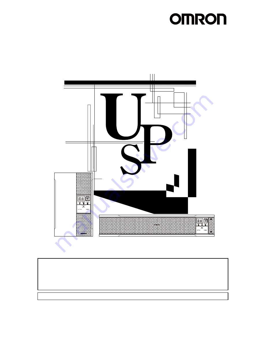
background image


Uninterruptible Power Supply UPS 

BA75T/BA100T/BA100R 

Instruction Manual 

BA75T/BA100T

BA100R


  This manual provides important safety-related information. Thoroughly read and understand this 

manual before installing and using the product. 

  Keep this manual in a convenient location so that you can refer to it whenever necessary. 

  The contents of this manual are subject to change without notice. 

  The warranty is included with the product. 


使用说明书


中文使用说明书请参照

8 Note of Chinese”


Содержание BA100R

Страница 1: ...safety related information Thoroughly read and understand this manual before installing and using the product Keep this manual in a convenient location so that you can refer to it whenever necessary T...

Страница 2: ...computer systems main communication equipment public transportation systems and so on Equipment with the same level of importance For equipment that greatly affects the safety of people and maintainin...

Страница 3: ...teries 2 SYMBOL This symbol indicates earth ground This symbol indicates turning on off UPS 3 INTERNAL BATTERY Internal battery voltage is 24VDC for BA75T BA100T BA100R 4 TEMPERATURE RATING The maximu...

Страница 4: ...processing of the devices when a power failure occurs 6 Using the contact signal functions Check the operation 3 Check and start operation Charge the battery Operate 3 Check and start operation The UP...

Страница 5: ...t 29 2 2 1 Connecting a device to the power supply output 29 2 3 Connecting the AC input 31 2 3 1 Connecting to the input terminal block 31 3 Check and start operation 34 3 1 The name and function for...

Страница 6: ...Toperformshutdownprocessingofthedeviceswhenapowerfailureoccurs 77 5 1 The outline on the UPS monitoring software 77 5 1 1 UPS monitoring software function list 77 5 1 2 The supported OS of the UPS mon...

Страница 7: ...Table of Contents 7 Troubleshooting 85 8 Note of Chinese 86 9 References 95 9 1 Specifications 95 9 2 Dimensions 96 9 3 Battery life 101 9 4 China RoHS Information 102 BA75T BA100T BA100R 6...

Страница 8: ...eliability and safety are required as listed below This unit is designed and manufactured for use with FA or OA equipment such as personal computers Medical equipment or system that may cause death di...

Страница 9: ...tenance on the connected devices follow the above instructions to ensure safety Do not connect devices such as dryers some solenoid valves etc which have a half wave rectifier that allows only half cy...

Страница 10: ...of the unit may operate which may stop the output The wiring of the plug strip heats up which may cause a fire Do not pinch or sharply bend the cable Do not fold or knot the cable Doing so may cause...

Страница 11: ...pply of commercial power Do not use the unit in a closed place and do not cover the unit Doing so may cause abnormal heating or a fire Depending on the operating environment hydrogen gas may be genera...

Страница 12: ...t is in operation the power output of his unit does not stop and power is supplied from the receptacle Do not disassemble repair or modify the unit Doing so may cause an electric shock or a fire If fl...

Страница 13: ...l energy still remains inside the spent battery Do not dispose of batteries in a fire The batteries may explode Dispose of used batteries according to the instructions Do not use a new battery and an...

Страница 14: ...s de l intervention sur les batteries a Retirer les montres bagues et autre objets en m tal b Utilisez des outils manche isol c Utilisez des gants et des chaussures isolant d Ne pas laisser des outils...

Страница 15: ...ity or a power failure due to instantaneous voltage drop may be detected If this unit is used for an inductive device such as a coil or motor check the operation beforehand With some types of devices...

Страница 16: ...Performing the withstand voltage test with the ground wire connected may damage the surge absorption element built into the power supply input circuit Storing Storing the battery in UPS charge for at...

Страница 17: ...ents are included and there is no damage found on their appearance If you should notice defects or anything wrong contact us OMRON Electronic Systems Equipments Customer Support Center BA75T BA100T BA...

Страница 18: ...le with EIA JIS 19 inch racks BAP100RS 2 Upright stand for BA100R BAP100R Upright stand for BA75T BA100T BAP100T CD ROM PowerAct Pro UPS monitoring software Simple Shutdown Software and UPS service dr...

Страница 19: ...onnection and 3 Check and start operation that provides the details Front view BA75T BA100T BA100R Air vent Operation panel Air vent Operation panel 1 2 3 4 5 6 7 8 A B E G D C F A Status indicator B...

Страница 20: ...minal block G Input surge protection GND H Power supply output receptacles Backup is performed during power failure I Cooling fan air vent A Cooling fan air vent B RS232C port C Contact signal port D...

Страница 21: ...00V input Power supply relay Charging circuit Rectifier high power factor converter Step up converter Inverter sine wave Filter Commercial power bypass output Output switching 4 ms max Control circuit...

Страница 22: ...device make a record of the serial number of this device The product serial number is required when contacting us about the device The serial number S N is inscribed on the bottom left side of the rea...

Страница 23: ...2 Installation and connection 2 1 Installation Incorrect Positions BA75T BA100T BA100R 22...

Страница 24: ...lation BA100R Air vents are facing upward Ba careful not to get your fingers caught when arranging the unit Correct Positions Note Upright stand for BA100R BAP100R is necessary for this position Incor...

Страница 25: ...it on the lower part of the rack Dropping it may result in injury Be sure to use the supplied mounting screws Use of long screws other than those supplied for case mounting may damage inside the unit...

Страница 26: ...d EIA rack fixing nuts M5 and 8 EIA JIS rack fixing screws M5 to securely fasten the front the side displaying L or R and the back of the support angles to the server rack 3 The screw holes are locate...

Страница 27: ...es of the UPS 4 4 4 The support angles cannot be attached to special EIA JIS racks 5 Place the UPS on the support angles and push it completely into the rack 5 and use the 2 included EIA JIS rack fixi...

Страница 28: ...R Horizontal installation Attach the included rubber feet for horizontal installation and position the unit horizontally For stationary horizontal installation make sure that this product does not sli...

Страница 29: ...tallation and connection 2 1 Installation BA75T BA100T Upright installation Use the upright stands 1 and M3 flat head screws 4 included with the rated product when you want to fix it BA75T BA100T BA10...

Страница 30: ...shown in the Safety precautions of the beginning of this manual 1 Disconnect the AC Input Plugs of all devices you want to back up such as your PC and modems from a wall outlet commercial power sourc...

Страница 31: ...tly Plug of connected device Plug of connected device Plug of connected device Connect the grounding wire of connect devices to Input surge protection GND of the UPS Connect the grounding wire to Inpu...

Страница 32: ...r installation and connection When connecting the AC input directly from a power switchboard make sure that the wiring work is performed by a qualified electrical engineer with Type II certification o...

Страница 33: ...able size 2 mm2 AWG14 L N Amount of stripped wire 6 to 8 mm Tightening torque 1 36 N m 12 lb in G Tightening torque 1 36 N m 12 lb in 4 Fix the terminal block cover with the screws and then turn the c...

Страница 34: ...Electrical Code Part I C22 1 Disconnect switch shall be provided by others for AC output circuit Reference The unit was charged before shipment but it may have self discharged during shipment resulti...

Страница 35: ...switch G Buzzer Pause Test switch Enlarged view of the operation panel 3 1 2 The meaning of each LED Sign of the figure LED Color Name Status Lit Not lit B Green Power supply output LED The power sup...

Страница 36: ...OFF and then turn on the AC input Use a fine pointed tool such as a small screwdriver to maneuver the switch s lever 1 2 3 4 5 6 7 8 ON Bit Function to set OFF side ON side 1 Setting for beeper sound...

Страница 37: ...unit shuts down using the shutdown software or contact signal BS signal the unit automatically starts and begins to output when the commercial power is restored ON Does not automatically start when po...

Страница 38: ...nd or more Setting switch 4 is valid when the auto startup after recovery from power failure setting Setting switch 2 is set to OFF auto restart is performed This setting mode is valid only after the...

Страница 39: ...c of Remote on off signal Setting switch 5 Factory setting OFF OFF UPS start shutdown process when detecting close condition of remote input signal ON UPS start shutdown process when detecting open co...

Страница 40: ...grid is within the voltage frequency range of ECO mode see the table below UPS will transfer to ECO mode and working in the bypass Table ECO mode range Input AC Voltage 10 of the nominal output volta...

Страница 41: ...0 5 second intervals ON OFF 0 5second 2 second intervals 2 second ON OFF 1 second intervals 1 second ON OFF 4 second intervals 4second ON OFF Continuous Continuous ON OFF Stopping the beep sound When...

Страница 42: ...play appears on 7 segment LED indicates blinking 3 Bring all the connected devices into operation Including devices connected to the AC outlet of your PC However operate the connected devices in a way...

Страница 43: ...atus Indicator Beep Output Description Intermittent 4 second intervals ON Backup is operating due to power failure or AC input error Output will stop if Battery Mode continues Intermittent 1 second in...

Страница 44: ...turn the beeper ON OFF 7 Reconnect the AC input to the commercial power source Status indicator returns to its normal state and the beeping sound stops The status is as shown below Status indicator D...

Страница 45: ...en the self diagnostic test finishes successfully switching to AC output from commercial power is performed and normal operation starts When the self diagnosis test finishes normally the unit enters t...

Страница 46: ...lert the user See also Setting switch 1 can be used to turn the beeper ON OFF indicates blinking Icon Beep Output Description Intermittent 4 second intervals ON Backup is operating due to power failur...

Страница 47: ...y Mode the battery life may be significantly shortened Press and release the Power switch of the UPS and then the Power switch turns OFF The power output from the UPS stops at the same time Additional...

Страница 48: ...or AC input error 1 When Power switch is ON 8 Intermittent 4 second intervals OFF Discharging In Battery Mode due to power failure or AC input error Output will stop if Battery Mode continues Perform...

Страница 49: ...an the times described below commercial power continues to be supplied through bypass operation Note 1 When connection capacity is at 110 or higher Bypass operation begins promptly Reduce the number o...

Страница 50: ...abnormal drop in output voltage Note 1 Same as above 28 bypass Continuous OFF Stopped charging due to abnormal rise in battery charge voltage When the battery discharges bypass output is performed Th...

Страница 51: ...hop of purchase or the OMRON Electronic Systems Equipments Customer Support Center 35 Continuous OFF Stopped charging due to abnormal rise in battery charge voltage Turn off AC input 36 Continuous OFF...

Страница 52: ...at the set voltage with no relation to the input voltage 2 Maximum backup time setting Maximum backup time can be set Setting range 0 to 90 minutes Default setting 0 minute 3 Reboot battery voltage s...

Страница 53: ...tor and the beeper ON OFF ON OFF ON OFF ON OFF ON OFF ON OFF ON OFF Battery Low signal BL Trouble signal TR Backup signal BU Deteriorated battery signal WB Backup power supply stop signal BS Remote ON...

Страница 54: ...supply output is OFF even if the Power switch is ON 1 When the Buzzer Pause Test switch is briefly pressed for less than 1 second the next item is displayed Output voltage Maximum backup time Reboot...

Страница 55: ...ond and then release it Operation D pressing the Buzzer Pause switch 5 second or more and then release it Operation E turning off the Power switch B B B B B B B B B B C C A E C C B B B Output 110V Out...

Страница 56: ...arge 20 Charge 90 Delay 0 2 min Delay 0 5 min Delay 1 min 10 step Delay 0 min Default Delay 2 min Delay 10 min Disable 1 min step BS signal delay DBS setting Display current setting Charge 0 Default R...

Страница 57: ...nal delay DBU setting Display current setting Current state of BL signal Current state of TR signal Current state of WB signal Current state of BU signal Dry contact logic LDC setting Display TR signa...

Страница 58: ...the unit and performs a test to check for battery deterioration Use the procedure below to check whether a circuit failure has occurred inside the unit and whether battery replacement is required The...

Страница 59: ...obtain an estimation of the initial value of the backup time This is also applied to checking the battery 1 Convert the total capacity power consumption of the connected devices to watts W For the in...

Страница 60: ...up time 25 C Initial Value Backup time table Time unit Minutes BA75T Connection capacity W 20 50 100 200 300 400 Backup time Minutes 200 109 56 23 14 9 BA100T BA100R Connection capacity W 20 50 100 20...

Страница 61: ...sustained beep release the switch In Commercial Power Mode Power switch ON When the beeper changes from intermittent beeps to a sustained beep release the switch If you do not reset the battery life c...

Страница 62: ...aries depending on your storage use environment and backup frequency The nearer the end of the life is the more rapidly deterioration proceeds Refer to the below shown reference data Battery life for...

Страница 63: ...r wrench to loosen turn counterclockwise the 2 screws at the top of the front panel of the unit until they turn freely 1 Lift the front panel up and pull toward you to remove 2 Loosen the 2 screws wit...

Страница 64: ...el at the bottom of the battery pack and remove the battery pack Caution for maintenance Do not hold the connector or cable of the battery pack Use the red tape on the top of the battery pack which is...

Страница 65: ...PS as far as it will go Replacement battery pack BA75T BA100T Model BAB100T 6 Attach the plate cover in order of 1 to 2 Use a screwdriver to securely tighten clockwise the screw you removed 3 Do not p...

Страница 66: ...s operation is stopped but this sound is not abnormal 1 2 Enlarged view of the connector Insert the con nector s groove into the holder Connect by holding here 8 Attach the front panel to the unit 1...

Страница 67: ...witch ON When the beeper changes from intermittent beeps to a sustained beep release the switch If you do not reset the battery life counter a battery deterioration alarm may occur faster than the exp...

Страница 68: ...and pull the connector apart 2 1 2 Remove the connec tor from the holder Disconnect by holding here Enlarged view of the connector 3 Turn the screw that fix the plate cover counterclockwise to remove...

Страница 69: ...or or cable of the battery pack Use the red tape on the top of the battery pack which is 10 cm from the inner edge of the battery to gauge how much further you need to pull the battery to remove it Ho...

Страница 70: ...the cable with the plate cover 2 1 Tighten the screw 3 7 Insert the battery connector until it is locked 1 Install the battery cable in the cable holder 2 Note You may hear a pop sound when you connec...

Страница 71: ...life counter after replacing the battery Press and hold the Buzzer Pause Test switch of the UPS for 10 seconds or longer to reset the battery life counter Resetting is complete when bJ is displayed Pe...

Страница 72: ...commercial power Caution for replacing the fan When this product is used in compliance with UL standards or CE marking do not replace the fan Fan replacement does not comply with UL standards or CE m...

Страница 73: ...ver above the fan on the back of the unit 1 Remove the fan cover 2 Loosen the 2 screws 1 2 Remove the fan cover 2 Use a screwdriver to loosen turn counterclockwise and remove the 4 cooling fan screws...

Страница 74: ...recess 1 Use a screwdriver to securely tighten turn clockwise the 4 removed screws 2 When doing so make sure the cable does not become pinned under the fan s cover Tighten the 4 screws 2 1 Insert the...

Страница 75: ...the back of the unit 1 Remove the fan cover 2 Loosen the 2 screws 1 2 Remove the fan cover 2 Use a screwdriver to loosen turn counterclockwise and remove the 4 cooling fan screws and the fan guard 1...

Страница 76: ...recess 1 Use a screwdriver to securely tighten turn clockwise the 4 removed screws 2 When doing so make sure the cable does not become pinned under the fan s cover Tighten the 4 screws 2 1 Insert the...

Страница 77: ...zene They cause deformation or discoloration 2 Removing dust from the input terminal block and output terminal block of the UPS Stop all the connected devices and the UPS and disconnect the AC input f...

Страница 78: ...Simple functions standalone Network management applications Advanced functions network support OS standard UPS service Simple Shutdown Software download PowerAct Pro optional Required options sold sep...

Страница 79: ...n programs can be launched 9 Event log save Information of events that occur on the UPS power supply problems setting changes occurrences of failure etc are saved as a log 10 Data log save Data of inp...

Страница 80: ...08 R2 Windows XP Windows Server 2003 Windows Server 2003 R2 Windows Vista Windows Server 2008 Simple Shutdown Software download The most recent version can be downloaded from our website http www omro...

Страница 81: ...p www omron co jp ese ups download category_u htm For more information refer to the manual of this soft ware 5 2 3 How to connect 1 Connect the UPS to a computer Cable Included connection cable RS232C...

Страница 82: ...when the battery is dead If a period of 3 months is exceeded you start operation by supplying commercial power and pressing the Start Switch However if the battery is dead you may not be able to star...

Страница 83: ...ife counter expires Battery Replacement Signal output WB Goes ON when the test determines that battery replacement is necessary due to deterioration or when the battery life counter goes off scale 6 1...

Страница 84: ...ON 5 to 15 VDC LOW OFF 0 5 VDC or less Input current 2 to 18 mA Remote ON OFF Voltage between terminals 5 VDC Current when closed 10 mA max 6 1 6 Contact Signal circuit Signal output BL TR BU WB UPS S...

Страница 85: ...d Remote ON OFF circuit Example of remote ON OFF Remote ON OFF Remote ON OFF UPS side 6 1 8 Precautions and notes for the use of the Contact Signal Notes When connecting a device such as a relay that...

Страница 86: ...the UPS if it is a long or thin cable Does not turn ON when Power switch is pressed The unit does not start up when the input power supply voltage frequency is abnormal The status indicator displays...

Страница 87: ...8 Note of Chinese 8 Note of Chinese UPS UPS 1 UPS FA OA Windows BA75T BA100T BA100R 86...

Страница 88: ...8 Note of Chinese 2 FA OA A VCCI A BA75T BA100T 12 5 BA100R 13 BA75T BA100T BA100R 87 8...

Страница 89: ...8 Note of Chinese AC AC100V 110V 115V 120V 50 60Hz AC UPS 10 90 0 C 40 C 25 85 BA75T BA100T BA100R 88...

Страница 90: ...8 Note of Chinese 5cm AC 25 5 30 4 AC AC AC AC BA75T BA100T BA100R 89 8...

Страница 91: ...8 Note of Chinese ON OFF AC INPUT PROTECTION 1mA AC UPS AC UPS BA75T BA100T BA100R 90...

Страница 92: ...8 Note of Chinese BA75T BA100T BA100R 91 8...

Страница 93: ...8 Note of Chinese AC UPS 25 25 6 40 2 AC AC DC250V BA75T BA100T BA100R 92...

Страница 94: ...8 Note of Chinese UPS 100V http www fa omron com cn AC AC 50 60Hz 3 3 3 Pb BA75T BA100T BA100R 93 8...

Страница 95: ...8 Note of Chinese UPS 1 OS 1 OS BIOS POWER MANAGEMENT Disable 1 MICRON Millennia MME BIOS Restore on AC Power Loss Power On BIOS BA75T BA100T BA100R 94...

Страница 96: ...ration 50 60 Hz 0 5 Backup operation 50 60 Hz 0 5 Waveform Commercial operation Sine wave Backup operation Sine wave Distortion rate 6 max Rectified load at rated output 3 max Resistance load at rated...

Страница 97: ...9 References 9 2 Dimensions 9 2 Dimensions Unit mm Tolerance 2mm BA75T BA100T BA100R BA75T BA100T BA100R 96...

Страница 98: ...9 References 9 2 Dimensions Unit mm Tolerance 1mm Upright stand for BA75T 100T BAP100T BA75T BA100T BA100R 97 9...

Страница 99: ...9 References 9 2 Dimensions Upright stand for BA100R BAP100R BA75T BA100T BA100R 98...

Страница 100: ...9 References 9 2 Dimensions Rubber feet BA75T BA100T BA100R 99 9...

Страница 101: ...9 References 9 2 Dimensions Using Ear brackets BAP100RS BA75T BA100T BA100R 100...

Страница 102: ...3 5 years 5 years BA series Basically the ambient temperature have a high influence on the battery life The periodic recharges are required even if the battery is stored The battery self discharges e...

Страница 103: ...9 References 9 4 China RoHS Information 9 4 China RoHS Information BA75T BA100T BA100R 102...

Страница 104: ...No part or whole of this manual may be reproduced without permission The contents of this manual are subject to change without notice Corporation K1L D 14006A...

Отзывы: