4.3.8 Sensor Setup (continued)
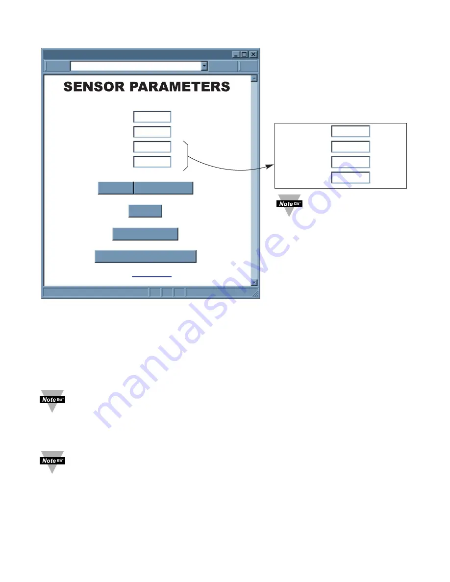
Figure 4.20 Sensor Parameters
Sensor Name:
Name of this Connector/Transmitter.
Update (Seconds):
How often this sensor is sending its data to the Receiver. This
update corresponds to the sampling rate configured by using the Configuration Wizard.
For detailed steps on how to configure the sampling rate, please refer to
Section 4.1 of
the UWTC Manual.
Non zero update rate will enable success calculation and lost
detection features. Update rate should reflect the actual blinking interval in order to
enhance the accuracy of success calculation and lost detection.
Update on the webpage means how often the Receiver expects a reading
coming from a Connector/Transmitter. The Receiver uses this Update to detect
lost condition and calculate success rate. It is purely used by the Receiver only,
and the Connector/Transmitter does not recognize the Update on the webpage.
Therefore, changing Update will not change the actual sample rate stored on
the Connector/Transmitter.
For a more accurate success rate and lost packet information, it is necessary to
change the default "update second" to the actual sampling rate of the
Connector/Transmitter. If you desire to lock this information in your Receiver,
DIP switch
#1
should be turned
ON
. Otherwise, in the case of a power outage
the default "update second" will go back to default.
Offset:
If it is determined that the readings are slightly off, the user can manually assign
numerical values to adjust the readings for temperature (in ºC) , humidity (in percentage),
and dewpoint (in ºC). The offset value can either be a positive or a negative number with
one decimal point
Sensor #2, Group A
SENSOR PARAMETERS
http://192.168.1.200
Address
Main Menu
Sensor Name
LAB 100
Select Another Group
Reset Sensor
Cancel
Update
0
Update
Reset Value
(seconds)
Offset1 (xxxx.x) 0
Offset2 (xxxx.x) 0
(C)
(C)
30
Update
0
(seconds)
Offset1 (xxxx.x) 0
Offset2 (xxxx.x) 0
(C)
Offset3 (xxxx.x) 0
(C)
(%)
If there is an RH
sensor, this section is
slightly different.


