7 |
M 5 7 9 0
3 GW-001 Hardware Overview
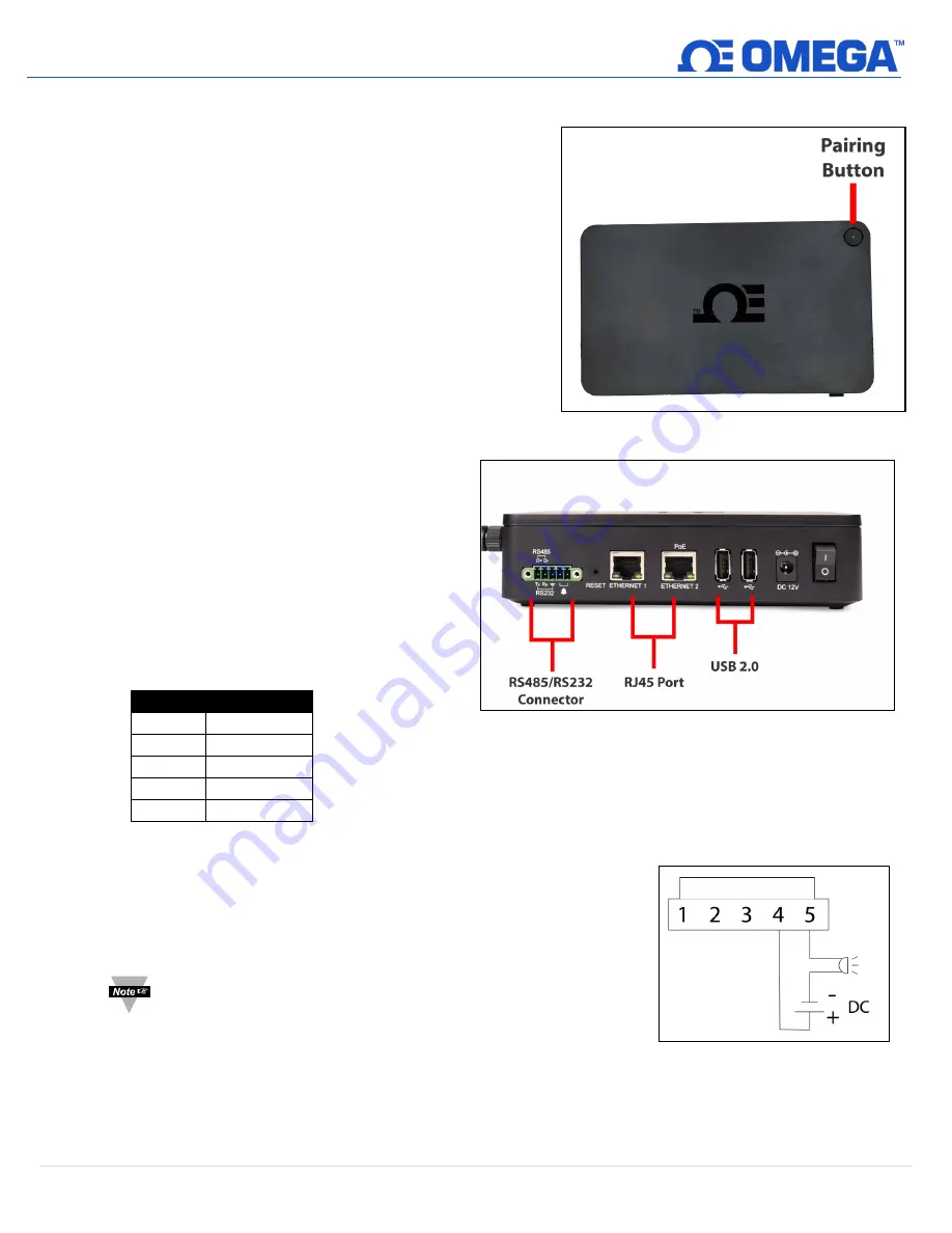
GW-001 series gateways offer the following connector and pairing
options to pair sensing devices to the Gateway (connector options
vary per model):
•
Smart Sensor one-button pairing
•
USB 2.0 Connector
•
Serial Data and Alarm 5-pin screw terminal
•
RJ45 connector for local network and Internet access
3.1
Smart Sensor Pairing
Pairing a Layer N Smart Sensor to your Layer N Gateway is made
easy with one-button pairing. Simply press the pairing button on
your gateway and press the pairing button on your Smart Sensor
to connect the two. Your Smart Sensor will now be visible on your
Layer N Cloud or OEG web interface.
3.2
USB 2.0 Connectors
The USB 2.0 connector is used to connect Layer N
Smart Probes with a Layer N IF-001 Smart Interface
Cable directly to your gateway.
3.3
Serial Data and Alarm Connector
The 5-pin terminal can accept RS232 or RS485 inputs
from authorized Omega accessories and devices such
as OM240, CN616A, and DP612. The 5-pin screw
connector on the gateway is labeled as follows:
Pin
Description
Pin 1
TX (D+)
Pin 2
RX (D-)
Pin 3
GND
Pin 4
Alarm (N/O)
Pin 5
Alarm (N/O)
Contact Omega or visit our website to see other compatible devices.
3.3.1
Alarm Relay Wiring
The 5-pin screw terminal can be used to connect a peripheral alarm
relay that will be triggered if the gateway loses network connection
to the Layer N Cloud or OEG.
Note:
This alarm will not detect a cabling or wiring issue. The alarm
will sound if the Gateway cannot reach the Layer N Cloud or
OEG network.
3.4
RJ45 Port
An RJ45 port is provided for local-network and Internet access, can be used for ModBus TCP devices, and some models
offer a Power over Ethernet feature.
Figure 1: Smart Sensor to Gateway pairing button
Figure 2: GW-001 Series input connectors (varies by model)
Figure 3: Alarm relay wiring diagram


