

CDi-16B - Installation and operating manual
www.omega-air.si
8
11
12
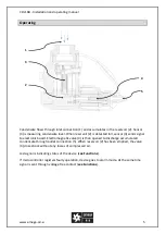
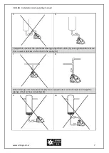
In case there are problems with inflow, it is necessary to install a venting line (12). In this
case back connection is used as inlet and upper connection is used as air ventilation. Venting
line must never be installed as it is on pictures 9, 10 and 11.
Warning: Upper and back connections cannot be used as condensate inlet at the same
time.
13
14
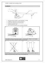
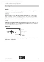
STANDARD INSTALLATION
Upper connection = Inlet
Back connection = Closed
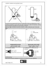
VENTING LINE INSTALLATION
Upper connection = Air vent
Back connection = Inlet
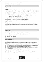
15a STANDARD WIRING
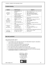
15b WIRING WITH ALARM (wires are
numbered)
Electrical wiring
Please ensure that the installation is carried out according to the valid regulations
Brown: L - Phase
Blue: N - Neutral
Yellow/Green: PE - Earth/Ground
5 – Alarm Output -
4 – Alarm
3 – Mains
2 – PE
1 – Mains


