6
Technical Specifications
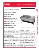
• LEG. Supports the equipment.
• ADJUSTABLE FEET. Used to adjust the level of the equipment.
•
DRIP TRAY. A tray that collects grease and oil. This tray can be removed for cleaning. It is recommended to
have water by in the drip tray to reduce flare-ups and smoking.
• PILOT LIGHT ACCESS HOLE. Allows access to the pilot light.
• GAS CONTROL KNOB. Used to set or adjust the temperature of the grilling surface.
• GRILL GRATES. Cooking surface.
Model
Style
Fuel
Manifold Pressure
B.T.U. per Hour
CE-CN-1219-G
4 Dual Burners with
Individual Control
Natural Gas
4.0” W.C.
112,000
Propane (LP)
10” W.C.
*Shipped setup for Natural Gas and includes a kit conversion for LPG.
Installation
WARNING: Fire Hazard
NEVER attempt to force or repair a stuck control valve. Contact your Authorized Omcan Service
Agency for repairs. Forced or improperly repaired valves pose the risk of fire and/or explosion.
WARNING: Fire and Explosion Hazard
If the pilot light should be extinguished, turn off the gas shut-off valve. Allow the appliance to
vent for five minutes before attempting to re-light.
INSTALLATION TO BE DONE BY LICENSED GAS PROFESSIONALS ONLY.
SET UP
1. Remove all packing material and tape, as well as any protective plastic from the equipment.
2.
Place the equipment in the desired position and height.
3.
Install the four (4) legs onto the equipment.
4.
Clean and dry the equipment thoroughly before using.
The installation of this equipment must conform with local codes, or with the National Gas Code, ANSIZ223.1/
NFPA 54, or the Natural Gas and Propane Installation Code, CSA B149.1, as applicable.
• The equipment and its individual shutoff valve must be disconnected from the gas supply piping system
during any pressure testing of that system at test pressures in excess of ½ psi (3.5 kPa).
• The equipment must be isolated from the gas supply piping system by closing its individual manual shutoff
valve during any pressure testing of the gas supply piping system at test pressures equal to or less then ½
psi (3.5 kPa).
Clearance and positioning around the equipment:
• This equipment must be installed adjacent to non-combustible surfaces only with a minimum spacing of
Содержание CE-CN-1219-G
Страница 15: ...15 Parts Breakdown Model CE CN 1219 G 37524...


