41
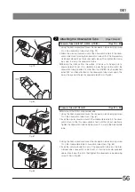
Fig. 59
6-2 TV Observation
}The following four methods are available for TV observation.
1. Attaching the video camera onto the side port
2. Attaching the video camera to the U-TR30H-2 trinocular observation tube H
3. Attaching the video camera onto the IX2-LBPC C-mount unit for lower back port (To be installed by the manufacturer)
4. Attaching the video camera onto the IX2-TVR/IX2-TVRAC bottom TV port unit (To be installed by the manufacturer)
1
Attaching the Camera on the Side Port
}The side port provides primary observation images that are brighter and higher in resolution than those obtained with the
trinocular observation tube H.
· Compatibility with various mounts from different manufacturers can be obtained by using the IX2-SPT straight photo tube
+ TV system for the BX series or by using a TV adapter for the BX series. However, this does not apply to the U-TVCAC and
U-DPT.
· For the installation of the IX2-SPT, see page 38.
· For the TV adapter systems for the BX series, refer to the instruction manual for the TV adapter to be used.
2
Attaching the Camera on the Trinocular Observation Tube H
(Fig. 59)
· Compatibility with various mounts from different manufacturers can be obtained by attaching the IX-SPT straight photo
tube on the U-TR30H-2 trinocular observation tube H and adding a TV adapter system for the BX series.
· A C-mount or F-mount video camera cam be attached by attaching the U-CMT C-mount adapter or U-FMT F-mount
adapter onto the IX-TVAD TV adapter.
Installation and Parfocal Adjustment of IX-TVAD TV Camera
1. Using the Allen screwdriver, loosen the clamping screw
1
on the trinocular
observation tube H.
2. Fit the IX-TVAD TV adapter
2
into the straight photo tube and tighten the
clamping screw
1
. (Fig. 59)
3. Firmly screw the U-CMT C-mount adapter
3
or U-FMT F-mount adapter
4
into the IX-TVAD TV adapter
2
. (Fig. 59)
4. Attach a compatible TV camera on the U-CMT or U-FMT.
<<
Parfocal Adjustment of Observation Image and Monitor Image
>>
1. Adjust the eyepiece to bring the specimen into focus.
2. Lightly loosen the clamping screws
1
and
5
. (Fig. 59)
3. While observing the monitor image and holding the U-CMT
3
or U-FMT
4
stationary, rotate the IX-TVAD
2
. Tighten the clamping screws
1
and
5
when the monitor image is in focus. (Fig. 59)
1
2
3
4
5

