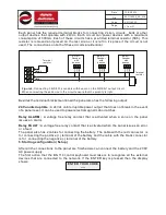
Besides the terminal blocks mentioned the panel also has the following output:
24V uninterruptible :
A 24Vdc uninterruptible power output that does not break in the event
of a panel reset. It can be used to power electromagnetic door latches.
Relay ALARM :
A voltage free relay contact that is activated when a zone on the panel
issues an alarm.
Relay FAULT :
A voltage free relay contact that is activated when the panel issues an error
or a fault.
The panel also has 2 cables for connecting the battery. The cable with the red connector is
for connecting the positive (+) terminal of the battery and the cable with the black connector
is for connecting the negative (-) terminal of the battery.
5. Starting configuration( Setup)
After all the connections to the panel are finished we can connect the battery and the 230V
AC
power supply.
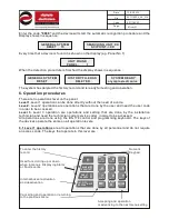
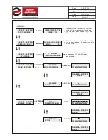
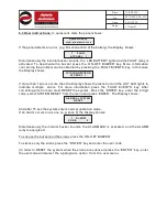
The first action that the BS-114 control keyboard must take is to recognize all the external
devices that are connected to the network. If the ENTER key is pressed then the display
shows
:
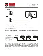
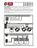
Each panel has the required terminal blocks for connecting 2 siren circuits, bells or other
output devices that operate with 24Vdc. Each circuit can power devices with a maximum
consumption of 600mA. Each of these circuits has a pre-fitted terminal resistor (5K6). This
resistor is removed and placed on the last siren or it is left in it’s place if the circuit is not
used. The connections on both of these circuits are identical.
F
igure 6.
Connecting 3 BS-531 sounders with beacon on the SIREN 1 output circuit.
When connecting these device to the circuit ensure that the polarity is right.
SIREN 1
SIREN 2
5
Κ
6
5
Κ
6
Terminal
resistor
Terminal
resistor
BS-531
Sounder
with
beacon
GND
12V
24V
BS-531
Sounder
with
beacon
GND
12V
24V
BS-531
Sounder
with
beacon
GND
12V
24V
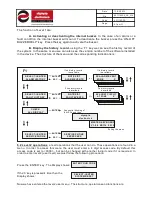
ENTER YOUR CODE
----
7
from
21
921116000
Date
File
Code
Page
921116000_09_016
13/03/2013
Содержание BS-116
Страница 1: ......


