2HA/2HB
1-5-21
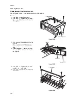
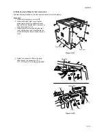
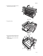
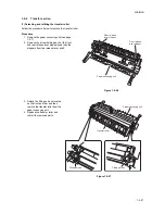
8. Remove the two screws holding the exit unit
and then pull out the unit a little.
Figure 1-5-46
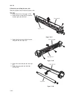
9. Remove the exit tray.
Figure 1-5-47
10. Remove the four screws and detach the two
connector and then remove the laser scan-
ner unit.
11. Replace the laser scanner unit and refit all
the removed parts.
Figure 1-5-48
Exit unit
Exit tray
Laser scanner
unit
Connector
Connector
Содержание d-Copia 1600
Страница 1: ...SERVICE MANUAL Published in October 2005 842HB110 First Edition d Copia 1600 d Copia 2000...
Страница 3: ...Revision history Revision Date Replaced pages Remarks...
Страница 4: ...This page is intentionally left blank...
Страница 10: ...This page is intentionally left blank...
Страница 14: ...2HA 2HB 1 4 30 This page is intentionally left blank...
Страница 20: ...2HA 2HB 1 4 30 This page is intentionally left blank...
Страница 126: ...2HA 2HB 1 4 30 This page is intentionally left blank...
Страница 162: ...2HA 2HB 1 4 30 This page is intentionally left blank...
Страница 180: ...2HA 2HB 1 4 30 This page is intentionally left blank...
Страница 213: ...INSTALLATION GUIDE FOR THE 300 SHEET CASSETTE...
Страница 220: ...INSTALLATION GUIDE FOR THE DOCUMENT PROCESSOR...
Страница 231: ...INSTALLATION GUIDE FOR THE DUPLEX UNIT...
Страница 239: ...INSTALLATION GUIDE FOR THE Printing System X...
Страница 242: ......

