background image

US-ENG- 18

US-ENGLISH

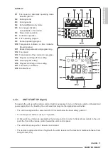
3.4 -  OPERATING THE UNIT

3.4.1 - 

OPERATIONAL MODES - TURNING THE UNIT ON/OFF

•  Button 

T1

 is used to switch the unit off (stand-by mode) or to switch the unit back on. 


an eProm contained in the unit’s control board system settings are memorized when the unit is turned 
off.

  If the unit will not be used for an extended period of time it should be de-energized by turning off 

the main power supply or pulling the plug from the wall outlet.

3.4.2 - 

WELL BEING KEY (AUTOMATIC OPERATING)

•  Button 

T2

 is used to allow the unit to provide optimal comfort in the space being conditioned. Based on 

the temperature in the room, the unit will automatically set the operating mode (cooling, ventilation or 
heating if available), the temperature setting and fan speed.

3.4.3 - 

COOLING MODE

•  In this mode, the unit dehumidifies and cools the room. Activate this mode by pressing button 

T4

 (run 

mode selector) until the “snowflake” symbol 

D3

 is displayed. the desired temperature and fan speed can 

now be selected.

•   After a maximum 3 minute delay (depending when the compressor ran last) the compressor will start, 

providing cooling to the space. Startup of the compressor is indicated by leD B being illuminated (green).
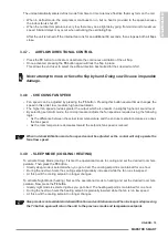
3.4.4 - 

DEHUMIDIFICATION MODE

in this mode the unit lowers the humidity level in the space. 

•  This function is very useful during the shoulder months between cooling and heating seasons, particularly 

on rainy days when the temperature is moderate, but the humidity in the space is high, causing occupant 
discomfort.

•  In this mode room temperature and fan speed settings are ignored and as such no temperature and fan 

speed indications are displayed.

•  Activate this mode by pressing button 

T4

 (run mode selector) until the “droplet” symbol 

D4

 and automatic 

ventilation symbol 

D1

 are displayed.

In dehumidification mode it is normal for the unit to function intermittently.

3.4.5 - 

FAN MODE

•  When used in this mode the unit does not perform any function in regards to temperature and air humidity 

control in the room.

•   Activate this mode by pressing button 

T4

 (run mode selector) until the fan symbol 

D1

 is displayed. in fan 

mode you can select the fan speed.

3.4.6 - 

HEATING/ DEFROST MODE

this mode is only available on heating pump (HP) models. 

•  To activate heating mode press button 

T4

 (run mode selector) until the “sun” symbol 

D2

 is displayed. the 

required temperature and fan speed can be selected.

•   After a maximum of 3 minutes the compressor should start, and unit provides heat to the space. The start 

of the compressor is indicated by leD B being illuminated (green).

Содержание Maestro Smart

Страница 1: ...SMART ENG INSTRUCTIONS FOR INSTALLATION USE AND MAINTENANCE...

Страница 2: ......

Страница 3: ...nit peut tre utilis e par des enfants d au moins 8 ans et par des personnes ayantdescapacit sphysiques sensoriellesoumentalesr duites oud pourvues de l exp rience ou des connaissances n cessaires cond...

Страница 4: ...orelfabricante por su servicio de asistencia t cnica o por personal con cualificaci n similar con el fin de prevenir cualquier riesgo para el usuario final 5 La instalaci n la primera puesta en marcha...

Страница 5: ...RT FRA ENG DIRECTIVES D INSTALLATION D UTILISATION ET D ENTRETIEN INSTRUCTIONS FOR INSTALLATION USE AND MAINTENANCE ESP INSTRUCCIONES DE INSTALACI N USO Y MANTENIMIENTO FRA ESP ENG 1 2 H C L A D G E B...

Страница 6: ...3 A 4 5...

Страница 7: ...min 300mm min 12 8mm 8 6 7 9 H G G min 200mm min 8 10 11 G 6a...

Страница 8: ...12 F D F G 13 14 6mm 15 16 F...

Страница 9: ...19 17 20 18 E E E 21...

Страница 10: ...H L A L 24 22 23 25 26 27...

Страница 11: ...32 30 31 J1 P1 P1 P2 28 29 33 9...

Страница 12: ...34 10 9 35 3 F 36 37 F1 F2 F1 F2...

Страница 13: ...sate water during an emergency 13 2 6 roUtine maintenanCe 13 2 6 1 Cleaning the air filter 13 3 USE AND MAINTENANCE 14 3 1 WarninGS aBoUt eQUiPment USe 14 3 2 DeSCriPtion of tHe WarninG Panel 14 3 3 U...

Страница 14: ...rstosituationsinwhichyoushouldinformtheServiCedepartmentinthecompany CUSTOMER TECHNICAL SERVICE 1 800 408 5196 techsupport olimpiasplendidusa com Index Paragraphs marked with this symbol contain very...

Страница 15: ...user this section contains useful information for understanding the use and programming of the unit and the most common maintenance recommendations 2 This document contains proprietary information pro...

Страница 16: ...on the labels affixed inside the unit and use common sense and follow the safety regulation enforced in the place of installation 10 Always wear personal protection devices when servicing the unit The...

Страница 17: ...rial The units are shipped complete and in perfect condition when leaving the manufacturing plant However we suggest that you perform the following checks a Upon receipt check if the package is damage...

Страница 18: ...WILL BE INSTALLED Before selecting an air conditioner or heat pump it is essential to make an accurate calculation of the heat load including sensible and latent gains for cooling mode and for heat pu...

Страница 19: ...d not be installed in a position where the airflow is directed towards occupants in the conditioned space Never force open the supply air flap Do not place any other object on the air grille that may...

Страница 20: ...ied out incorrectly When installing heat pump models if no condensate line are built into the wall it will be necessary to drill a hole through the wall as shown on the installation template 2 4 2 PRE...

Страница 21: ...ompletely outwards reopen the grille being careful to keep your fingers inside the louvres h turn the grille until the louvres are fully horizontal and tilted downwards i Pull the chain tensioning the...

Страница 22: ...trical power supply is equipped with efficient grounding and with adequate protections against overloading and or short circuits a type 15 AT delayed fuse or other devices with equivalent functions ar...

Страница 23: ...he pin P1 on the right hand side of the fap e insert the fap into the unit by inserting the pin into the top hole on the right hand side in the opening P2 and the flap s left hand hole on the upper pi...

Страница 24: ...below to determine the cause DESCRIPTION LED D GREEN LED C YELLOW LED B GREEN LED A RED overtemperature of internal heat exchanger Hti off off on off overtemperature of external heat exchanger Hte of...

Страница 25: ...more thorough cleaning can be performed using non acidic environmentally friendly detergents and use a damp cloth to gently clean the surface of the unit To prevent unnecessary service calls from the...

Страница 26: ...unit is in heating mode it may go into defrost mode to melt any ice that could have formed on the condenser coil While it is doing this the machine keeps running but does not heat the space The defro...

Страница 27: ...the unit there may be interference Electronic and fluorescent lighting may interfere with communications between the remote control and the unit If not being used for an extended period of time remov...

Страница 28: ...programs T7 Button for increasing or decreasing the temperature time settings T8 Button for activating the free CoolinG air change system not available in this model T9 ON OFF button for oscillating f...

Страница 29: ...Clock program setting D16 Program switching on time setting D17 Low battery notification D18 minutes timer 3 3 3 UNIT START UP fig 34 to operate the unit using the remote control it will be necessary...

Страница 30: ...B being illuminated green 3 4 4 DEHUMIDIFICATION MODE in this mode the unit lowers the humidity level in the space This function is very useful during the shoulder months between cooling and heating...

Страница 31: ...evel By selecting automatic mode the microprocessor adjusts the fan speed as required using the following logic As the difference between the actual room temperature and the end user setpoint increase...

Страница 32: ...h the timer programming 3 5 3 TIMER SETTING PROGR 1 AND PROGR 2 fig E1 it is possible to set one or both the timer programs to set the times for starting and stopping the unit proceed as follows a Pre...

Страница 33: ...ng the shades Do not obstruct the air flow from either the inlet or outlet of the unit Obstructing airflow results in reduced performance and will eventually damage the unit 3 7 Diagnostic Recommendat...

Страница 34: ...mote control and the unit s reception confirmation sound will not work when you attempt to issue a command if this is the case replace the batteries The unit does not cool or heat adequately the tempe...

Страница 35: ...Starting the unit verify Supply voltage to the unit _______ install batteries in remote Control Start Unit to verify operation and record requested values below the following values are to be recorde...

Страница 36: ...Changes in the appearance of the product that do not affect product performance 14 increases in utility costs and additional utility expenses 15 a completed data sheet available on www olimpiasplendi...

Страница 37: ......

Страница 38: ......

Страница 39: ......

Страница 40: ...262089C 2 Contact Information olimpia Splendid USa 66 White Street floor 501 new York nY 10013 USa Phone fax 800 408 5196 email customerservice olimpiasplendidusa com...

Отзывы: