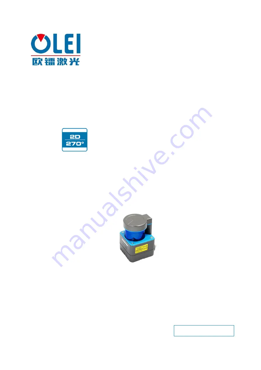
OLEI LR-1BS3 Скачать руководство пользователя страница 1


Sensing Reality! 


LiDAR Sensors 

LR-1BS3/5 Series 

User Manual 


This manual is only applicable to LR-1BS3/3D/5/5D 


Please read this user manual for best product performance before using the product. 

Be sure to keep this manual properly for future reference. 


OMEN-1BS35-202202 

Содержание LR-1BS3

Страница 1: ...1BS3 5 Series User Manual This manual is only applicable to LR 1BS3 3D 5 5D Please read this user manual for best product performance before using the product Be sure to keep this manual properly for future reference OMEN 1BS35 202202 ...

Страница 2: ...ew 6 6 2 Definition of Header 6 6 3 Definition of data block 6 6 4 Data conversion 7 7 Parameter configuration 8 7 1 Parameter configuration of web page 8 7 2 Configuration of OlamViewer 10 8 Troubleshooting 10 Appendix A Data packet 11 Appendix B Mechanical Dimensions 11 Appendix C Example of Electrical Connection 12 Appendix D Firmware Upgrade 12 Appendix E Suggestions on Mechanical Installation...

Страница 3: ...es will have to be observed during operation Opening the screws of the LiDAR housing will invalidate any warranty claims against OLEI Repairs may only be performed on the LiDAR by trained and authorized OLEI service personnel 3 Product introduction The LR 1BS3 5 is an opto electronic laser scanner that electro sensitively scans the perimeter of its surroundings at a single plane with the aid of la...

Страница 4: ...terface of LR 1BS3 5 Bottom mounted There are two M3 screw holes hole depth is 3mm at the bottom of the LiDAR Figure 2 Bottom mounting interface of LR 1BS3 5 4 2 Pin and wire color assignments LR 1BS3 5 is equipped with a Power IO connection and an Ethernet connection ...

Страница 5: ... red 3 GND_IO gray 4 VCC_IO brown 5 OUT0 blue Table 1 Definition of Power IO connection Figure 4 Diagram of Power IO connection 4 2 2 Ethernet connection NO definition 1 TxData Send 2 TxData Send 3 RxData receive 4 RxData receive Table 2 Definition of Ethernet connection Figure 5 Diagram of Ethernet connection Ethernet Power IOcable Power IO Ethernet ...

Страница 6: ...mputer IP must be set up in the same subnet without any conflict The host port is 2368 by default The factory default settings are as follows Computer IP 192 168 1 10 Computer subnet mask 255 255 255 0 The default factory settings of LiDAR are as follows LiDAR IP 192 168 1 100 LiDAR subnet mask 255 255 255 0 The operation steps are as follows Figure 6 Step 1 of computer IP setting Figure 7 Step 2 ...

Страница 7: ...d at its surface The reflection is detected in the LiDAR s receiver by a photodiode The LiDAR calculates the distance to the object from the transit time required by the light from emission of the beam to receipt of the reflection The calculation method is as follows 𝐷 𝐶𝑇 2 D Detection distance T flight time C speed of light 6 Data packet format LR 1BS3 5 can realize laser point cloud data transmi...

Страница 8: ... version currently 0x0200 6 1 Distance ratio actual distance value distance reading distance ratio mm 7 3 Brand code expressed in capitalized letters and numbers fill in with 0 in the end if isn t long enough 10 12 Sales model string ending with 0 22 2 Internal model code 24 2 hardware version 26 2 Software version 28 4 Timestamp unit ms 32 2 Bit 14 0 Rotation rate BIT 15 rotation direction 0 cloc...

Страница 9: ...1mm 6 result 4625mm 6 4 3 Calculation of signal strength The signal strength calculation method of LR 1BS3 5 is shown in the following example 1 Obtain the signal strength value 0x11 0x12 2 interchange of high bits and low bits 0x12 0x11 3 Combine into an unsigned hexadecimal number 0x1211 4 Converted to decimal number 4625 5 Results 4625 Offset length Description 0 2 Angle unsigned integer valid ...

Страница 10: ...g scanning frequency is 10 15 20 25HZ and click SetConfigs to confirm Set the LED indicator ON and OFF through Led Marquee and click Set Configs to confirm Set the ON and OFF of the LiDAR safety function through Safe Area and click Set Configs to confirm Select input mode of safe bank trough Safe bank input GPIO mode is not available for 1BS3 5 Set the mode of the LED indicator through Led Mode Se...

Страница 11: ...User Manual LR 1BS35 OMEN 1BS35 202202 9 Figure 11 Parameter configuration of web page Figure 12 Advanced configuration page ...

Страница 12: ...ether the IP settings on the data receiver are correct Try to use third party data scraping software to verify whether data could be obtained normally Verify whether only one LiDAR software is enabled Verify whether firewall of the data receiver is disabled or if there are other security software or processes blocking data transmission Please contact OLEI if the above conditions are normal LiDAR c...

Страница 13: ...User Manual LR 1BS35 OMEN 1BS35 202202 11 Appendix A Data packet Appendix B Mechanical Dimensions ...

Страница 14: ...s LiDAR Figure 14 Icon D 1 Software features For 2D LiDAR LR 1BS series firmware upgrade D 2 Surroundings for software Windows 7 8 10 Net framework 4 5 2 D 3 Software operation 1 Connect the LiDAR correctly Check whether the LiDAR communication is normal 2 Click the File Information box or drag the firmware file in The relevant information of the corresponding firmware is prompted after the firmwa...

Страница 15: ...ed to fix the LiDAR be as flat as possible 5 The positioning column on the mounting base should strictly follow the depth of the positioning column at the bottom of the LiDAR and should not be higher than 4mm It is recommended to use aluminum alloy mounting base for better heatdissipation 6 When installing the LiDAR if the LiDAR has contact mounting surfaces on both top and bottom please make sure...

Страница 16: ...2 14 Figure 16 Placement of two LiDARs opposed to each other Figure 17 Crosswise placement of two LiDARs Figure 18 Placement of two LiDARs with parallel offset Figure 19 Placement of two LiDARs with parallel offset one of these upside down ...

Страница 17: ...ment of two LiDARs upside down parallel offset Figure 21 Placement of two LiDARs with parallel offset one of these upside down The emission position of the 2D LiDAR from the reference plane is as follows Figure 22 Light emission position of LR 1BS LR 1B LR 1F ...

Страница 18: ...rface of the LiDAR and then wipe it with a dry and clean fiber cloth If there are mud or other blocky foreign matter on the surface of LiDAR first spray clean water on the surface of the dirty part on the LiDAR to remove the mud and other foreign matter Note please do not wipe off the mud directly with a fiber cloth as this may scratch the surface especially the surface of the protective cover The...

Страница 19: ...pecifications etc without notice Hangzhou Ole systems Co Ltd No 35 Jiuhuan Road Jianggan District Hangzhou City Zhejiang Province China Web www ole systems com Email sales ole systems com TEL 86 400 102 5850 Copyright Hangzhou Ole systems Co Ltd Release 2022 02 ...

Отзывы: