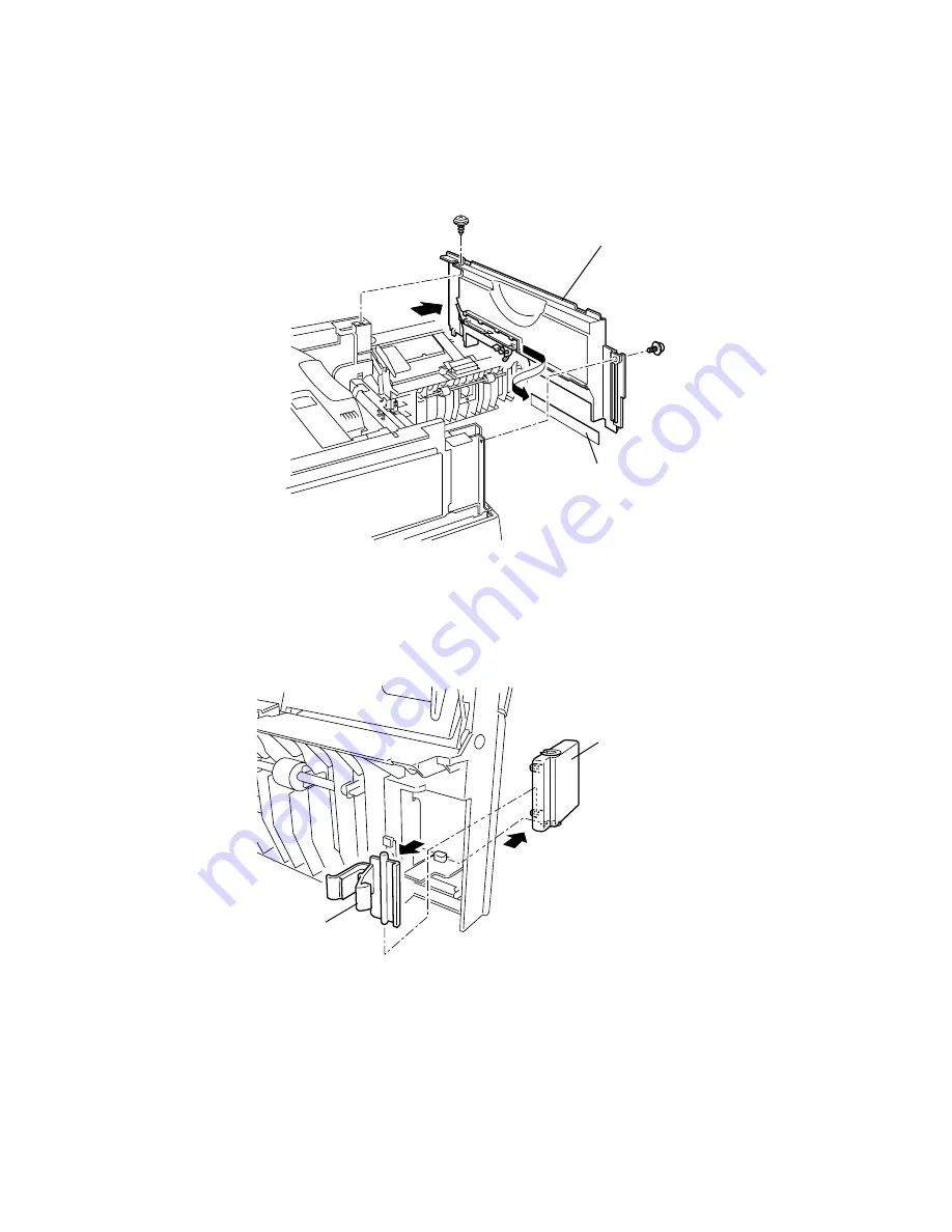
Oki OKIOFFICE 1200 Скачать руководство пользователя страница 144

5-11 

RIGHT COVER 

1. Remove the FRONT COVER. 

2. Remove the REAR COVER. 

3. Remove the two right cover mounting screws. 

4. Slide the line cover and disconnect the harnesses of the TOS sensor and the HPES sensor. 

5. Then remove the RIGHT COVER. 


Right cover

Line cover


COVER OPENER 

1. Open the jam access cover. 

2. Release the COVER LEVER. 

3. Remove the COVER OPENER. 
 

Cover opener

Cover lever


Содержание OKIOFFICE 1200

Страница 1: ...OKIOFFICE 1200 1600 FIELD ENGINEERING MANUAL Version 2 0 11 June 2002...

Страница 2: ...nstructeur Mettre au rebut les batteries usag es conformement aux instructions du fabricant Germany only VORSICHT Explosinsgefahr bei unsachgem en austausch der batterie Ersatz nur durch denselben ode...

Страница 3: ...lmistajan ohjeiden mukaisesti ALL Areas CAUTION Replace only with the same or equivalent type recommended by the manufacturer Dispose of used IC Package according to the manufacturer s instructions Ge...

Страница 4: ...ecording Paper Feed Path 2 13 2 8 Image Processing 2 13 2 8 1 Drum Charge 2 14 2 8 2 Drum Exposure 2 14 2 8 3 Development 2 14 2 8 4 Image Transfer 2 15 2 8 5 Residual toner distribute 2 15 2 8 6 Fusi...

Страница 5: ...DRAM Clear 3 77 3 17 Clear Life Monitor 3 77 3 18 Clear Optional Data 3 77 3 19 Set Service Code 3 78 3 20 Life monitor maintenance 3 78 3 21 JP1 JP2 Battery Backup 3 79 3 22 Update the software 3 80...

Страница 6: ...5 5 2 2 PCBs 5 13 5 2 3 Sensors 5 24 5 2 4 Scanning section 5 25 5 2 5 Printer section 5 37 5 3 Adjustment 5 49 5 3 1 Adjustment of Retard roller pressure 5 49 Section 6 Options 6 1 Memory Upgrade 6...

Страница 7: ...iv Packaging contents 6 22 Installation 6 22 Setting of the Paper Size 6 25...

Страница 8: ...1 1 Product Description The OKIOFFICE 1200 and OKIOFFICE 1600 is Multi function product with flat bed scanner and Group 3 and V 34 HDX modem facsimile machine Documents are printed on plain paper usin...

Страница 9: ...t Scanning resolution Transmission horizontal vertical in dots mm in lines mm Normal 8 3 85 Fine 8 7 7 Super fine 8 15 4 Greyscale 8 7 7 Transmission horizontal vertical in dots mm in lines mm Normal...

Страница 10: ...er kit has been installed Recording paper capacity Paper cassette 1st cassette 500 sheets 2nd cassette option 500 sheets Bypass tray Plain paper 50 sheet Postcard Transparency 20 sheets Envelopes 1 sh...

Страница 11: ...2 1 Section2 Machine Composition 2 1 OKIOFFICE 1200 Interconnect Block Diagram 1 2 OKIOFFICE 1200 Connection Diagram 1 2...

Страница 12: ...2 2 OKIOFFICE 1200 Interconnect Block Diagram 2 2 OKIOFFICE 1200 Connection Diagram 2 2...

Страница 13: ...2 3 OKIOFFICE 1600 Interconnect Block Diagram 1 2 OKIOFFICE 1600 Connection Diagram 1 2...

Страница 14: ...2 4 OKIOFFICE 1600 Interconnect Block Diagram 2 2 OKIOFFICE 1600 Connection Diagram 2 2...

Страница 15: ...ll times Memory FLASH MEMORY SRAM SDRAM FLASH MEMORY The FLASH MEMORY contains all program instructions for unit operation SRAM The SRAM which is backed up by a lithium battery is used to store user p...

Страница 16: ...D LAMP SDRAM PRINTER CONTROL 1 MOTOR CONTROL SYSTEM G A1 SYSTEM G A2 SRAM SDRAM PRINTER CONTROL 2 FBS MOTOR ADF MOTOR HIGHT VOLTAGE POWER SUPPLY UNIT PRINTER UNIT POWER SUPPLY UNIT SDRAM PCB MAIN 1 fo...

Страница 17: ...LAR PCB 24V 5V GND 12V 12V S DP NCU PCB block diagram Major components of the NCU CML relay Connects the telephone line to the phone or fax S relay Used to send dial pulse signals in pulse dialing OH...

Страница 18: ...ding to instructions received from the heater control circuit If an over current is sensed in the secondary circuit power is interrupted Power supply unit block diagram The power supply unit has two o...

Страница 19: ...2 9 2 5 Sensors 2 5 1 Sensor Locations The following illustration shows the relative positions of the machine s sensors TXIL HOME END APS DS1 DS2 PSS TOS PDS PES HPES COVER SW DRUM SW CASOP JCOP...

Страница 20: ...witch PSS Paper set sensor Detects paper feeding out of cassette tray Photo interrupter PDS Paper discharge sensor Detects paper pass at paper exit Photo interrupter PES Paper empty sensor Detects pre...

Страница 21: ...document reaches the scan wait position The machine uses the distance from DS2 to the scan wait position and the diameter of the feed roller to determine the number of rotations necessary to feed the...

Страница 22: ...o follow DS1 DS2 Mirror A Mirror B Mirror C CCD Lens Press roller A Feed roller A Feed roller B Separator roller Pick up roller Retard roller Press roller A Exit roller Press roller B Document scannin...

Страница 23: ...coming data is received from the telephone line by the NCU and sent to the main control PCB The modem located on the main control PCB demodulates the data The data is then sent to the printer for imag...

Страница 24: ...own over the drum and projects light onto the drum surface When the document is to be printed individual elements in the LED print head turn on and expose the drum where ever a dark area should appear...

Страница 25: ...e Drum and the Image Transfer Roller Hight voltage unit output PC Drum Image transfer roller 2 8 5 Residual toner distribute The residual toner must be removed from the drum This step does not actuall...

Страница 26: ...tects the surface temperature of the Heater Roller and inputs that analog voltage into the Main Control PCB Corresponding to this data the Heater Lamp ON OFF signal is output to the Heater ON OFF swit...

Страница 27: ...Roller is maintained at 185 C After printing the printer turns to standby mode The fuser kept at low temperature 3 Standby mode The Heater Roller maintained at approx 100 C 4 Sleep mode In this mode...

Страница 28: ...Access the printer maintenance mode Print Program Mode List Program key 8 Prints a list of the unit s programming modes Test Modes Program key 9 Allows the technician to perform a series of diagnosti...

Страница 29: ...ess to move the cursor to the right Press the 0 or 1 on the numeric keypad to change the bit value Press ENTER to save the setting of the displayed parameter and advance to the next parameter Continue...

Страница 30: ...12 db 6 1 0 1 0 1 5 0 Non loaded cable compensation RX 0 0 1 1 0 db 4 db 8 db 12 db 4 1 0 1 0 1 3 2 1 0 Output attenuation See table below Note The setting of this switch is available only when settin...

Страница 31: ...table below Machine Parameter A 2 DTMF output level attenuation Switch 3 Switch 2 Switch 1 Switch 0 Attenuation 0 0 0 0 0 dB 0 0 0 1 1 dB Initial setting for OKIOFFICE 1200 0 0 1 0 2 dB 0 0 1 1 3 dB...

Страница 32: ...2 514 mm Initial setting OKIOFFICE 1200 11111110 215 138 mm 11111111 215 985 mm Machine Parameter A 4 Switch Initial Setting Adjust Usage Comments 7 6 5 4 3 2 1 0 Trailing edge document margin adjustm...

Страница 33: ...32MB capacity Machine Parameter A 8 and A 9 Factory use only Machine Parameter B 0 Switch Initial Setting Adjust Usage Comments 7 6 5 4 3 2 1 0 Leading edge document margin adjustment FBS Adjusts the...

Страница 34: ...00101011 36 421 mm Initial setting OKIOFFICE 1600 11111110 215 138 mm 11111111 215 985 mm Machine Parameter B 2 Switch Initial Setting Adjust Usage Comments 7 0 6 0 5 0 4 0 3 0 2 0 1 0 0 0 ADF scanner...

Страница 35: ...mm 10000100 2 0 mm 10000101 2 5 mm 10000110 3 0 mm 10000111 3 5 mm Minimum Machine Parameter B 4 and B 5 Factory use only Machine Parameter B 6 Switch Initial Setting Adjust Usage Comments 7 0 6 0 5...

Страница 36: ...00 mm 00000001 0 0847 mm 00000010 0 1694 mm 00111110 5 2514 mm 00111111 5 3361 mm Machine Parameter B 8 Switch Initial Setting Adjust Usage Comments 7 0 6 0 5 0 4 0 3 0 2 0 1 0 0 0 Trailing edge docu...

Страница 37: ...76543210 00000000 Darkest setting 00000001 00000010 Initial setting 00000011 00000100 Lightest setting Machine Parameter D 2 Switch Initial Setting Adjust Usage Comments 7 0 6 0 5 0 4 0 3 0 2 0 1 1 0...

Страница 38: ...witch 76543210 00000000 Darkest setting 00000001 00000010 Initial setting 00000011 00000100 Lightest setting Machine Parameter D 6 Switch Initial Setting Adjust Usage Comments 7 0 6 0 5 0 4 0 3 0 2 0...

Страница 39: ...FFICE 1200 Switch 76543210 00000000 Darkest setting 00000001 00000010 Initial setting 00000011 00000100 Lightest setting Machine Parameter E 0 E 9 Factory use only Machine Parameter F 0 Switch Initial...

Страница 40: ...OFFICE 1600 10001000 0 8 10010000 1 6 10011000 2 4 10100000 3 2 10111000 12 7 Minimum Machine Parameter F 2 Switch Initial Setting Adjust Usage Comments 7 6 5 4 3 2 1 0 Adjustment of the scanning stre...

Страница 41: ...4 0 3 0 2 0 1 0 0 0 Scanning contrast adjustment for copying Only for OKIOFFICE 1600 Switch 76543210 00111111 Darkest setting 00000010 00000001 00000000 Initial setting 11111111 11111110 11000000 Ligh...

Страница 42: ...0 2 0 1 0 0 0 Scanning slice level adjustment in Super Fine resolution for transmission Only for OKIOFFICE 1600 Switch 76543210 00111111 Darkest setting 00000010 00000001 00000000 Initial setting 111...

Страница 43: ...t point to print The plus setting increase the top margin and the minus setting decrease it Each setting changes by 0 042 mm Switch 76543210 Settings 01111111 5 3 mm Maximum 00000011 0 13 mm 00000010...

Страница 44: ...2 0 mm Initial setting 10000101 2 5 mm 10000110 3 0 mm 10000111 3 5 mm 10001000 4 0 mm Minimum Machine Parameter J 4 Switch Initial Setting Adjust Usage Comments 7 1 6 0 5 0 4 0 3 0 2 0 1 0 0 1 Print...

Страница 45: ...s to move the cursor to the right Press the 0 or 1 on the numeric keypad to change the bit value Press ENTER to save the setting of the displayed memory switch and advance to the next memory switch Co...

Страница 46: ...unit always dials a given number of seconds after going off hook Memory switch A 1 sets the number of seconds Memory Switch A 1 Dialer Switch Initial Setting Adjust Usage Comments 7 0 Dial pulse 0 No...

Страница 47: ...Fax Tel Ready mode Incoming calls are answered according to this setting regardless of the number of rings chosen in the User Settings If Silent Operation is enabled this setting will change to 2 rin...

Страница 48: ...e second DIS signal 4 0 V 29 Echo Protect tone 0 No 1 Yes International telephone lines equipped with echo suppression will cut the beginning portion of the transmitted information which may cause the...

Страница 49: ...T is received after DCS and TCF signals due to line echo increase the interval between DCS and TCF signals using this switch 4 0 75 ms 300 ms 450 ms 600 ms Switch 5 0 0 1 1 Switch 4 0 1 0 1 3 2 Output...

Страница 50: ...the ECM post message 2 0 ECM error retransmit time 0 200 ms 1 400 ms The time limit before the ECM error is retransmitted 1 0 Interval between DIS and DCS 0 0 0 ms 500 ms 1000 ms 1500 ms Switch 1 0 0...

Страница 51: ...at 0 if a T 4 1 or T 4 4 error occurs the unit will not retry the transmission 0 0 Action after EOR signal 0 Continue 1 Discontinue Sets action after receiving PPR four times at 2400 bps Memory Switch...

Страница 52: ...OKIOFFICE 1600 Note The maximum speed for OKIOFFICE 1200 is 14 4 kbps Memory Switch C 1 Reception Switch Initial Setting Adjust Usage Comments 7 0 Factory use only 6 0 Factory use only 5 0 Factory us...

Страница 53: ...each other compensate the group delay 1 0 Digital cable equalizer 0 Free 1 Hold When set to 1 become efficient for the line short break but become weak for the line noise It s available only for comm...

Страница 54: ...t Lenient 0 1 0 1 1 1 EYE Q check level at 0 0 1 1 0 0 4800 bps Strict Lenient 0 1 0 1 Memory Switch D 3 Reception Switch Initial Setting Adjust Usage Comments 7 0 Factory use only 6 0 Factory use onl...

Страница 55: ...fter dialing 0 1 sec 1 200 ms When dialing from the keypad phone line noise may occur as the CML relay switches on and off Set this switch to 0 to avoid this 5 0 DTMF tones heard through handset 0 No...

Страница 56: ...0 1 0 0 40 ms 0 1 0 1 50 ms 0 1 1 0 60 ms 5 1 0 1 1 1 70 ms 1 0 0 0 80 ms 1 0 0 1 90 ms 1 0 1 0 100 ms 1 0 1 1 110 ms 4 1 1 1 0 0 120 ms 1 1 0 1 130 ms 1 1 1 0 140 ms 1 1 1 1 150 ms 3 0 Off hook on h...

Страница 57: ...0 Switch hook time If the switch hook is quickly depressed and released switch to fax will occur This setting adjusts how quickly the switch hook activation must be Switch 3 2 1 0 Time 2 0 0 0 0 0 0...

Страница 58: ...0 0 1 1 1 7 sec 1 0 0 0 8 sec 1 0 0 1 9 sec 1 0 1 0 10 sec 1 0 1 1 11 sec 4 1 1 1 0 0 12 sec 1 1 0 1 13 sec 1 1 1 0 14 sec 1 1 1 1 15 sec 3 0 Number of seconds silent detection remains active This sw...

Страница 59: ...ec 3 0 CNG detect period after TAD answers Sets the period during which CNG is detected after the TAD answers an incoming call Switch 3 2 1 0 Time 0 0 0 0 0 sec 0 0 0 1 10 sec Initial setting 2 0 0 0...

Страница 60: ...nly 1 0 Factory use only 0 0 Beep if fax handset hang up 0 Yes 1 No Determines if your fax beeps when having left the fax s handset hanging up after communication Memory Switch G 6 Remote reception an...

Страница 61: ...rint check message 0 No 1 Yes To notify the user of an error a check message can be printed if a communication error occurs 0 0 Stop printing check message for a memory transmission by pressing the st...

Страница 62: ...nsmit Terminal Identifier TTI Subscriber ID etc are stored in the unit s Random Access Memory RAM This information is held by a battery back up when the power is lost This function does not clear the...

Страница 63: ...Individual Autodialer Attributes This function allows the user to configure an individual one touch or speed dial entry with the settings shown in Memory Switches B 0 B 1 B 2 and B 3 To set the indivi...

Страница 64: ...econd Echo Protect tone is placed prior to the training using G3 high speed modem training V 29 3 Maximum transmit speed kbps 2 4 4 8 7 2 9 6 12 14 4 16 8 19 2 21 6 24 26 4 28 8 31 2 33 6 2 0 0 0 0 0...

Страница 65: ...rint when transmitting from memory 0 No 1 Yes Will force a remote OKIOFFICE machine with memory receive capabilities to print directly This switch will prevent a memory overflow error at the remote un...

Страница 66: ...o 1 6 0 V 34 transmission Only for OKIOFFICE 1600 0 Yes 1 No Individual setting for V 34 transmission 5 0 Factory use only 4 0 ECM mode 0 On 1 Off Determines ECM mode ECM mode reduces document memory...

Страница 67: ...key to move the cursor to the right Press the 0 or 1 on the numeric keypad to change the bit value Press ENTER to save the setting of the displayed unique switch and advance to the next unique switch...

Страница 68: ...Factory use only 2 0 Factory use only 1 0 Factory use only 0 1 Factory use only Unique Switch a 1 a 9 Factory use only Unique Switch b 0 Transmission Switch Initial Setting Adjust Usage Comments 7 0...

Страница 69: ...o 1 Yes Transmit the sub address and box name of F code box with F code polling document 2 0 Factory use only 1 0 Retrieve document 0 No 1 Yes Retrieve the document received in F code SecureMail box b...

Страница 70: ...on when disable to detect first NSF in feeder transmission Unique Switch b 9 Factory use only Unique Switch c 0 Reception Switch Initial Setting Adjust Usage Comments 7 0 Factory use only 6 0 Factory...

Страница 71: ...etting 0 1 1 1 14 s 1 0 0 0 16 s 1 0 0 1 18 s 1 0 1 0 20 s 1 0 1 1 22 s 4 0 1 1 0 0 24 s 1 1 0 1 26 s 1 1 1 0 28s 1 1 1 1 30 s 3 1 TCF check time in 100 ms units If the TCF time is such that poor imag...

Страница 72: ...he remote fax number set to the block junk dial list 1 0 Factory use only 0 0 Call request when remaining memory size is small 0 No 1 Yes Setting this switch to 1 prompt call request to transmitter wh...

Страница 73: ...3000 baud symbol rate when communicating at V 34 Only for OKIOFFICE 1600 0 No 1 Yes 2 1 2800 baud symbol rate when communicating at V 34 Only for OKIOFFICE 1600 0 No 1 Yes 1 0 Factory use only 0 1 24...

Страница 74: ...nique Switch d 4 Switch Initial Setting Adjust Usage Comments 7 0 Symbol rate adjustment 0 No 1 Yes When re transmission occurs frequently set to 1 When set to 1 the re transmission may become not to...

Страница 75: ...dB 1 0 1 1 11 dB 1 1 0 0 12 dB 1 1 0 1 13 dB 1 1 1 0 14 dB 1 1 1 1 15 dB Unique Switch d 6 Modem Switch Initial Setting Adjust Usage Comments 7 0 Factory use only 6 0 5 0 Silent detection sensitivity...

Страница 76: ...ms 100 ms 200 ms 300 ms Switch 4 0 0 1 1 Switch 3 0 1 0 1 2 0 Factory use only 1 0 Factory use only 0 0 Factory use only Unique Switch d 8 d 9 Factory use only Unique Switch e 0 Scanner Switch Initia...

Страница 77: ...tory use only 1 0 Mirror carriage home position 0 FBS 1 ADF This switch is only effective when the unique switch E 2 bit 0 is set at 0 Determines the Mirror carriage home position 0 1 Mirror carriage...

Страница 78: ...e mirror carriage to the start of the scanning position which was set in Machine parameter B 0 Each setting changes by 0 0847mm Switch 3210 Settings 0111 0 5929 mm 0101 0 4235 mm 0100 0 3388 mm Initia...

Страница 79: ...1 1 11 mm 0 0 1 1 0 0 12 mm 0 1 0 1 0 0 20 mm 0 1 0 1 0 1 21 mm 0 1 0 1 1 0 22 mm 1 1 1 1 1 1 63 mm Unique Switch e 8 Scanner Switch Initial Setting Adjust Usage Comments 7 0 Factory use only 6 0 Fac...

Страница 80: ...scanning document by FBS Each setting changes by 1 mm Switch 5 4 3 2 1 0 Settings 0 0 0 0 0 0 0 mm Initial setting 0 0 0 0 0 1 1 mm 1200 0 0 0 0 1 0 2 mm 0 0 0 0 1 1 3 mm 0 0 0 1 0 0 4 mm 0 0 0 1 0 1...

Страница 81: ...Yes 0 1 Smoothing in Normal resolution in receive mode 0 No 1 Yes Smoothes the data scanned in each resolution mode Unique Switch f 1 Printer Switch Initial Setting Adjust Usage Comments 7 0 Factory u...

Страница 82: ...tch Initial Setting Adjust Usage Comments 7 1 Factory use only 6 0 5 1 Limit of the memory capacity in Reverse order print Determine the limit of the memory capacity for storing the received document...

Страница 83: ...range If you set the time to be shorter the print density will be light Switch 5 4 3 2 1 0 1 0 0 0 0 0 54 69 sec Darkest 1 1 0 0 0 1 25 17 s 1 1 0 0 0 0 26 91 s 1 0 1 1 1 1 28 65 s 1 0 1 1 1 0 30 38 s...

Страница 84: ...0 0 Silent detection 0 No 1 Yes Enables or disables silent detection during Ans Fax Ready mode Unique Switch g 1 g 6 Factory use only Unique Switch g 7 Remote reception and TAD interface Switch Initi...

Страница 85: ...olume OFF Low Medium Maximum 4 0 0 0 1 1 0 1 0 1 3 0 Priority of Speed Dial Tel Index key 0 Speed Dial 1 Tel Index When set to 0 Speed Dial index will appear first when pressing Speed Dial Tel Index k...

Страница 86: ...o answer On Off function will be added to the functions which can be registered in Soft keys 0 0 Factory use only Unique Switch h 4 Operation Switch Initial Setting Adjust Usage Comments 7 0 Factory u...

Страница 87: ...unter If the remote fax machine disconnects the phone line before the PC responses the CI signal the fax regards that the PC is off and then it will receive from the next call In this case increase th...

Страница 88: ...only 2 0 Priority of Printing the Check message on A5 Portrait 0 No 1 Yes When set to 1 A5 Portrait sized paper will be given priority to print the check message 1 0 0 0 Paper size of F4 sized paper...

Страница 89: ...within two main menu level Set Replace Counter Enter Service Call Enter 2 Press until Set replace counter appears in the LCD and then press ENTER 3 The LCD shows Replace Fuser Enter 4 If you replaced...

Страница 90: ...ch are outlined 3 9 Print Program Mode List This mode causes the unit to print a summary list of the unit s programming modes To print the program mode list press Program key 8 After printing the unit...

Страница 91: ...displays drum replaced One touch H displays total pages printed on current drum One touch I displays toner replaced count One touch J displays toner life One touch K displays fuser replaced count One...

Страница 92: ...1 Press Program key 9 then press ENTER Pattern 2 Press One touch A B C D E F or G to select the desired pattern Pattern A Printing The selected pattern will print continuously Note Press STOP to canc...

Страница 93: ...ine 1 Press Program key 9 three times then press ENTER BackgroundLevel Test Complete 3 10 5 Set Background Level The background level is an established threshold used to help measure the reflective ab...

Страница 94: ...press One touch A 01 H 08 as indicated in the following list A detailed explanation of each mode follows this list One touch A 01 Prints a list of the Factory Functions One touch B 02 LED test One to...

Страница 95: ...ill be displayed Key Indication in LCD Key Indication in LCD DOCUMENT RESOLUTION Document Resolution COPY RESET Copy Reset CONTRAST Contrast START Start DOCUMENT SIZE Doc Size STOP Stop PAPER SIZE NEX...

Страница 96: ...on completion press any key to return to the standby mode 3 12 6 DRAM Check This mode is used to test the DRAM memory or document memory Note When this test is performed an All DRAM Clear will be perf...

Страница 97: ...onal RS 232C port Important Before doing the RS 232C test connect the 2 pin and 3 pin of the RS 232C interface see step 1 below If not the RS 232C test does not operate correctly 1 Connect a special r...

Страница 98: ...ays and switches will appear in the display CML H L DP S C24 TONE BZ RI 4 The one touch keys are used to toggle the various relays and switches on and off as outlined on the following table When a rel...

Страница 99: ...CED tone press numeric key 9 The output signal will begin A different output signal can be selected by pressing corresponding numeric key and one touch key Note It may take several moments for output...

Страница 100: ...ps 27 2800 baud 26400 bps 27 12000 bps Note V 34 is available only for 1600 28 14400 bps 29 16800 bps 30 19200 bps 31 21600 bps 32 24000 bps 33 26400 bps 34 28800 bps 35 31200 bps 36 33600 bps 37 3429...

Страница 101: ...put test then press ENTER DTMF 4 Pressing a button on the numeric key or one touch key will produce DTMF tones according to the following table Numeric key Signal One touch key Signal 0 DTMF 0 941 Hz...

Страница 102: ...default setting is OFF not print the consumable sheet See Unique Switch H 3 to set ON this feature 3 15 1 Set consumable order sheet If using this feature you should be enter following items Distribu...

Страница 103: ...er s address and continue The LCD will show Address2 Upper _ Enter the customer s address for the Lower row The customer s address may be up to 30 characters in length 9 Press ENTER to save the custom...

Страница 104: ...a count of the pages scanned printed and transmitted along with the drum replacement count and total pages printed on the current drum This mode clears these counters 1 Press Program key H 08 Clear Li...

Страница 105: ...0000 by repeating steps 1 4 and entering 0000 in step 3 3 20 Life monitor maintenance When you replace the main control PCB you should register the previous several counter values of the life monitor...

Страница 106: ...of the printer operation time then press ENTER 15 The machine returns to its standby mode 3 21 JP1 JP2 Battery Backup Jumper JP2 on the main control PCB is used for battery back up of the DRAM Any do...

Страница 107: ...OM1 and ROM2 are set to the Flash ROM writer 4 Turn the power on 5 The Flash ROM writer erases the current program in the fax machine then writing the new program to the machine Flash Mem Write Prog E...

Страница 108: ...lat level surface The ambient temperature and relative humidity surrounding the unit should be 50 F to 89 6 F 10 C to 32 C at 20 to 80 humidity with no condensation The unit should be located in a wel...

Страница 109: ...r proper operation 3 Clean the exit roller using a lint free cloth moistened with a cleaning solution designed for use on rubber rollers Replace the exit roller if worm or damaged 4 Verify the fuser r...

Страница 110: ...ate if it is not released Then press PROGRAM E to turn off the mirror carriage carry mode 2 Check the setting of Unique SW E 2 bit 0 1 3 Verify that the timing belt doesn t out of joint 4 Check the op...

Страница 111: ...t the remote machine does not have closed network or block junk fax turned on 6 3 Transmit to another location 7 Check the operation of NCU PCB and the main control PCB 4 9 Receive Errors Symptom Chec...

Страница 112: ...sage will appear and the machine will abort the operation anyway instead you ll have to perform the job again from scratch The first page of the document jammed During the real time transmission or qu...

Страница 113: ...m the machine Note If you cannot remove the original document open the inner cover as shown at right then remove the document 3 Gently close the scanner cover making sure both sides are snapped down s...

Страница 114: ...o that you don t catch your hands possibly injuring them 1 Open the top cover 2 Open the printer cover 3 Remove the toner and drum cartridge Important Shield the drum cartridge from light especially s...

Страница 115: ...paper jam Note Avoid getting unfixed toner on your hands and clothes Open the side cover Pulling up the jam release lever to remove the jammed paper 5 Reset the toner and drum cartridge 6 Gently clos...

Страница 116: ...nt or where voltages may vary 6 Should not be installed near a direct heating or cooling source or vent 7 Should not be exposed to high dust concentration 8 Should not be exposed to direct sunlight 9...

Страница 117: ...age is faint or does not print solid Poor development Remove the toner cartridge and shake it a few times to redistribute the toner inside If the problem persists replace the toner cartridge Replace t...

Страница 118: ...LED print head Defective Drum If the drum surface for moisture condensation found leave drum in unit with power on to dry Replace the Drum Cartridge Poor image transfer Replace the Image Transfer Unit...

Страница 119: ...Replace the Fusing Unit Poor image transfer Replace the Image Transfer Unit Improper LED exposure Replace the LED Print Head Unit Poor scanning Clean the Contact Grass 4 12 9 Toner Smudges Symptom Bac...

Страница 120: ...ich is not same sized paper you told your Open Close Top Cover sized paper you told your machine is loaded Set correct sized paper or change the paper size setting Close Scanner Cover The cover indica...

Страница 121: ...You tried to store a document for polling in an F Code box which is set to be a security box Select an F Code box which is set to be a bulletin box then try again In Use in P OneTouch You tried to era...

Страница 122: ...sscode in your machine then retry again No PIN Number You selected Mode1 in the pin mask feature and tried to call an autodialer number in which no PIN has been entered or to call using numeric keypad...

Страница 123: ...trying to enter requires the use of the scanner which is already in use Wait for the fax to complete the scan then re try the desired command SecurityRx is Off You tried to turn the security reception...

Страница 124: ...to do Select Paper Size You tried to make a copy in the following conditions Paper size selection is set to Auto The bypass tray has the paper other than A4 A5 or F4 Paper cassette s runs out of pape...

Страница 125: ...r the transmitting unit is having difficulties R 1 2 Compatibility error The calling unit is attempting to poll a document that does not exist R 1 4 The STOP button was pressed during reception R 1 5...

Страница 126: ...ust the interval between DCS and TCF on Memory Switch B 1 If the problem persists try increasing the output levels on Machine Parameter A 1 T 3 1 The page counter in the fax machine detected a documen...

Страница 127: ...ssfeed or miscount Unable to reach remote machine after attempting specified number of redial Line is busy Remote machine was busy Remote machine didn t answer Check received documents Receive confirm...

Страница 128: ...e Inverter PCB 4 15 2 Please Call Service When certain machine problems occur a Please Call Service message will appear in the LCD When this message appears access the printer maintenance mode Service...

Страница 129: ...Check continuity of fuser unit If OK see step 4 if bad replace the fuser unit 4 Replace the power supply unit 5 Replace the fuser unit If the problem is not correct see step 6 6 Replace the main cont...

Страница 130: ...ontrol board Drum Fuse Error Symptom The fuse in the new drum cartridge does not disconnect when set the new drum cartridge Suggested corrective action 1 Verify the drum cartridge is set correctly 2 C...

Страница 131: ...o the Panel A PCB P1903 Panel A PCB P190A to the Harness to the main control PCB P19A Panel A PCB P190B to the Harness to the main control PCB P19B 5 Replace the associated PCBs and connector harness...

Страница 132: ...th a cleaner suitable for use on platen rubber rollers In steps 4 and 6 we ll call this the rollers cleaner The other with isopropyl alcohol 3 Open the scanner cover by holding the scanner cover relea...

Страница 133: ...LED print head If you find your fax recipients complaining that the faxes you receive or copy image quality are streaked the LED print head may be dirty Important Be careful not to put your hand betw...

Страница 134: ...ment 5 1 MAINTENANCE SCHEDULE 5 2 5 2 RE DISASSEMBLE 5 3 5 2 1 Covers 5 5 5 2 2 PCBs 5 13 5 2 3 Sensors 5 24 5 2 4 Scanning section 5 25 5 2 5 Printer section 5 37 5 3 ADJUSTMENT 5 49 5 3 1 Adjustment...

Страница 135: ...100 000 1 5 45 Feed roller BP 100 000 1 5 44 Exit roller P 100 000 1 5 41 Image Transfer Section Maintenance Cycle pages Parts Name Clean Replace QTY Reference Page Image transfer roller 60 000 1 5 41...

Страница 136: ...ODULAR PCB 5 15 POWER SUPPLY UNIT PSU 5 16 HIGH VOLTAGE POWER SUPPLY HVPS 5 17 CONNECT PRINTER PCB 5 17 PANEL A B C and LCD 5 18 CONNECT SCANNER PCB 5 19 BATTERY PCB 5 21 INVERTER PCB 5 22 LAMP 5 22 C...

Страница 137: ...5 38 RX MOTOR 5 38 DRIVE GEAR ASSEMBLY 5 39 TOS 5 39 PICK UP ROLLER MP 5 40 HPES 5 40 IMAGE TRANSFER ROLLER 5 41 FIXING UNIT 5 41 PDS Thermistor 5 42 EXIT ROLLER P 5 42 PES 5 43 PAPER PICK UP ROLLER...

Страница 138: ...p rear cover Harness holder Top left cover Contact glass Pane Top front cover Jam access cover Cover opener Front cover Panel cover One touch cover Tx side cover R Tx side cover F Tx cover Rx exit cov...

Страница 139: ...the top cover 2 Remove the two front cover mounting screw 3 Remove the FRONT COVER REAR COVER 1 Open the top cover 2 Remove the five rear cover mounting screws 3 Disconnect the speaker connector and...

Страница 140: ...nting screws and then remove the TOP RIGHT COVER 5 Remove the two top left cover mounting screws and then remove the TOP LEFT COVER Top Front Cover Top Rear Cover Harness holder Screw cover Screw cove...

Страница 141: ...2 Remove the four Tx cover mounting screws 3 Remove the TX COVER Tx cover TX SIDE COVER F 1 Open the platen cover 2 Remove the Tx side cover F mounting screw 3 Release the locking tab and then remove...

Страница 142: ...en the platen cover 2 Remove the three Tx side cover R mounting screws 3 Remove the TX SIDE COVER R Tx side cover R EXIT TRAY 1 Open the cassette 2 Remove the three exit tray mounting screws 3 Remove...

Страница 143: ...ION COVER A Option cover A RX EXIT COVER 1 Remove the EXIT TRAY 2 Remove the TOP LEFT COVER 3 Remove the OPTION COVER A 4 Remove the Rx exit cover mounting screw and then remove the RX EXIT COVER Rx e...

Страница 144: ...ht cover mounting screws 4 Slide the line cover and disconnect the harnesses of the TOS sensor and the HPES sensor 5 Then remove the RIGHT COVER Right cover Line cover COVER OPENER 1 Open the jam acce...

Страница 145: ...ugh 2 in PANEL A B C and LCD page 5 18 PLATEN COVER Perform the procedure of step 1 through 5 in CONNECT SCANNER PCB page 5 19 BOTTOM CORNER COVER Perform the procedure of step 1 through 2 in CONNECT...

Страница 146: ...5 13 5 2 2 PCBs Main control PCB NCU CCD PCB PSU HVPS Connect printer PCB Panel A PCB Panel B PCB Panel C PCB Connect scanner PCB Battery PCB Inverter PCB Connect ADF PCB...

Страница 147: ...Confirm the JP1 and JP2 on the main control PCB are set to ON 1 Remove the rear cover 2 Remove four shield plate mounting screws 3 Disconnect all connectors on the main control PCB 4 Remove two main...

Страница 148: ...connect all connectors on the NCU PCB 4 Remove the NCU PCB NCU PCB MODULAR PCB 1 Remove the REAR COVER 2 Remove four shield plate mounting screws and then remove the SHIELD PLATE 3 Disconnect all conn...

Страница 149: ...motor mounting screws and then remove the FAN MOTOR 3 Remove the duct mounting screw and then remove the DUCT Duct Fan motor 4 Disconnect two connectors on the PSU 5 Remove the two F G wires 6 Remove...

Страница 150: ...ews then remove the HVPS High voltage power supply CONNECT PRINTER PCB 1 Remove the REAR COVER 2 Remove two PCB shield mounting screws and then remove the PCB shield 3 Disconnect all connectors on the...

Страница 151: ...ounting screws and then remove the PANEL COVER Panel cover 3 Disconnect two connectors between PANEL A and B PANEL B and C 4 Disconnect the film harness of the LCD 5 Remove all PANEL PCB mounting scre...

Страница 152: ...CD LCD support LCD LCD spacer CONNECT SCANNER PCB 1 Remove the TOP FRONT COVER THE TOP RIGHT COVER and the TOP LEFT COVER 2 Remove the bottom corner cover mounting screw and then remove the BOTTOM COR...

Страница 153: ...ve the harness holder mounting screw and then remove the HARNESS HOLDER 5 Remove the PLATEN COVER assembly Harness holder Platen cover assembly 6 Remove two screw covers Then remove four top rear cove...

Страница 154: ...remove the CONNECT SCANNER PCB Connect scanner PCB BATTERY PCB 1 Perform the procedure of step1 through 6 in CONNECT SCANNER PCB page 5 19 2 Disconnect the connector on the BATTERY PCB and remove the...

Страница 155: ...mounting screws then remove the INVERTER PCB Lens cover Inverter PCB LAMP 1 Perform the procedure of step 1 through 3 in INVERTER PCB see above 2 Disconnect the connector for the LAMP on the INVERTER...

Страница 156: ...PCB 1 Remove the TX SIDE COVER R 2 Disconnect all connectors on the CONNECT ADF PCB 3 Remove the ground wire 4 Remove two CONNECT ADF PCB mounting screws and then remove the CONNECT ADF PCB Connect AD...

Страница 157: ...ME sensor END sensor page 5 33 APS Refer to ADF permit sensor page 5 29 DS1 Refer to TXIL ADF DS1 DS2 page 5 26 DS2 Refer to TXIL ADF DS1 DS2 page 5 26 PSS Refer to PSS page 5 46 TOS Refer to TOS page...

Страница 158: ...section TENSION PULLEY EXIT GEAR 24 SEPARATOR GEAR 22 TENSION PULLEY GEAR 16 36 GEAR 26 30 GEAE 48 IDLER PULLEY 17 50 17 PULLEY G26 50 17 PULLEY BELT INSTALLATION OF ADF SECTION FBS Motor BELT INSTALL...

Страница 159: ...ensor you want to remove DS1 DS2 TXIL ADF SEPARATOR ROLLER ASSEMBLY 1 Remove the TX COVER 2 Remove the E ring and then remove the separator gear 22 3 Remove two E rings and then remove the SEPARATOR R...

Страница 160: ...QUE LIMITER 1 Open the Scanner Cover 2 Remove the RETARD COVER 3 Remove the RETARD ROLLER Assembly Retard cover Retard roller assembly 4 Remove two E rings and then remove the TORQUE LIMITER with the...

Страница 161: ...OR Motor bracket Spring C Pulley 50 17 G26 FEED ROLLER A 1 Remove the TOP SIDE COVER R and F 2 Remove the ADF MOTOR 3 Pull out the PULLEY 50 17 G26 4 Remove the F G wire mounting screw 5 Remove the E...

Страница 162: ...INNER GUIDE A assembly Inner guide A assembly Feed roller A ADF PERMIT SENSOR APS 1 Remove the TX SIDE COVER F and R 2 Remove the Scanner Cover Assembly 3 Remove two APS BRACKET mounting screws and t...

Страница 163: ...canner Cover Assembly 4 Remove two INNER GUIDE B mounting screws and then remove the INNER GUIDE B 5 Remove the APS 6 Remove two E rings on the right and left of the FEED ROLLER B and then remove the...

Страница 164: ...e the TX SIDE COVER R 2 Remove two E rings and then remove the EXIT GEAR 24 and the Bearings Exit gear 24 3 Open the Platen Cover Remove two PLATEN SHEET mounting screws and then remove the PLATEN SHE...

Страница 165: ...5 32 4 Remove five PLATEN STAY B mounting screws and then remove the PLATEN STAY B Platen stay B 5 Remove two PRESS SPRING D 6 Remove the EXIT ROLLER Exit roller...

Страница 166: ...r C FBS MOTOR 1 Remove the TOP FRONT COVER the TOP RIGHT COVER and the TOP LEFT COVER 2 Remove the BOTTOM CORNER COVER 3 Remove the HINGE SCREW and the HARNESS HOLDER mounting screw and then remove th...

Страница 167: ...or brackect FBS Motor SCANNER ASSEMBLY 1 Remove the TOP FRONT COVER THE TOP RIGHT COVER and the TOP LEFT COVER 2 Remove the BOTTOM CORNER COVER 3 Remove the HINGE SCREW and the HARNESS HOLDER mounting...

Страница 168: ...screw 7 Remove two LENS COVER mounting screws and then remove the Flat Cable from the CCD PCB Belt retainer Lens cover Flat cable CCD PCB 8 Slide out the GUIDE ROD as shown below Then remove the SCAN...

Страница 169: ...5 36 KNOB 1 Open the TOP COVER 2 Remove the SPRING 3 Remove the small screw with a precision screwdriver 4 Pull out the KNOB Knob Spring...

Страница 170: ...Remove the CONNECT PRINTER PCB 3 Remove two COVER SWITCH mounting screws and then remove the COVER SWITCH Cover switch CASOP 1 Remove the REAR COVER 2 Remove the CONNECT PRINTER PCB 3 Remove the PSU...

Страница 171: ...NNECT PRINTER PCB 3 Remove the SOLENOID mounting screw and then remove the SOLENOID Solenoid RX MOTOR 1 Remove the REAR COVER 2 Remove the CONNECT PRINTER PCB 3 Remove the PSU 4 Remove four RX MOTOR m...

Страница 172: ...move the SOLENOID 3 Remove the four DRIVE GEAR Assembly mounting screws then remove the DRIVE GEAR Assembly Drive gear assembly TOS 1 Open the TOP COVER 2 Remove the Toner Cartridge and Drum Cartridge...

Страница 173: ...e RIGHT COVER 2 Remove the bearing and then remove the PICK UP ROLLER MP Pick up roller MP HPES 1 Remove the FRONT COVER the REAR COVER and the RIGHT COVER 2 Remove the PICK UP ROLLER MP 3 Disconnect...

Страница 174: ...G UNIT 1 Remove the toner cartridge and the drum cartridge 2 Remove the REAR COVER 3 Disconnect the connector P1302 and P1307 from the CONNECT PRINTER PCB and CN1 from the PSU Also remove the F G wire...

Страница 175: ...and then remove the PDS or the thermistor Fxing unit cover PDF Themistor EXIT ROLLER P 1 Remove the FIXING UNIT 2 Disassemble the FIXING UNIT to remove the EXIT ROLLER P Note Do not bend the PLATE SP...

Страница 176: ...sette completely 2 Remove the PES mounting screw under the cassette and then remove the PES Disconnect the connector PES PAPER PICK UP ROLLER 1 Pull out the cassette completely 2 Pull out the pick up...

Страница 177: ...Remove the FRONT COVER the REAR COVER and the RIGHT COVER 2 Remove four MP bracket mounting screws and then remove the MP BRACKET 3 Remove the Feed B Bearing and then slide out the FEED ROLLER BP Feed...

Страница 178: ...e CONNECT PRINTER PCB 4 Remove the DRIVE GEAR ASSEMBLY 5 Remove the HVPS 6 Remove the MAIN FRAME mounting screws Main frame 7 Remove the E Rings at the both side of the FEED ROLLER AP and FEED GEAR 16...

Страница 179: ...he PRESS SPRING B Remove the RELEASE LEVER and the PRESS ROLLER BP 3 Remove the PSS COVER and remove the screw Pull out the PSS and disconnect the connector PSS Press spring B Release lever Press roll...

Страница 180: ...ver 2 Remove the E rings on the both side and pull out the LED print head Disconnect two connectors LED print head JCOP 1 Open the Side cover 2 Disconnect the connector of the JCOP 3 Release the tab o...

Страница 181: ...5 48 BYPASS TRAY 1 Open the Side cover 2 To remove the BYPASS TRAY release the tab at the front side of the BYPASS TRAY first then release the other Bypass tray...

Страница 182: ...uncleanness adjust the Retard roller pressure Insert the precision screwdriver into the hole of the Inner guide A as illustration Then turn the separation pressure adjustment screw with referring the...

Страница 183: ...AR COVER and then remove the SHIELD PLATE 3 Attach the SPACER to the expansible MEMORY PCB 4 Connect the MEMORY PCB to the connector P16 on the unit s Main control PCB Spacer Memory PCB Spacer Memory...

Страница 184: ...8 MB 8MB 16384 KB 8 MB 24 MB OKIOFFICE 1600 only 32768 KB 9 Re attach the SHIELD PLATE and REAR COVER 10 Re plug the telephone line cord The following table shows the memory capacity Total memory Mem...

Страница 185: ...ion 1 Turn the fax machine off and remove the power cord and telephone line cord 2 Using a Phillips head screwdriver attach the cord holder and handset holder to the left side of the machine using the...

Страница 186: ...emove two screws on the RS 232C PCB and then attach the bracket to the RS 232C PCB with them Join the RS 232C PCB and the Connector PCB as shown below Note The bracket may have been attached to the RS...

Страница 187: ...slot Then use the mounting screw to attach the assembly 10 Re attach the shield plate 11 Re attach the option cover using its mounting screw 12 Re attach the rear cover using five mounting screws 13 A...

Страница 188: ...e Contents 2 TXD Transmitted data Data signal sent from computer to your fax 3 RXD Received data The data sent to computer by your fax 4 RTS Request to send Signal for request to send data 5 CTS Clear...

Страница 189: ...connection harness to the connector labeled P21 on the main control PCB Then re attach the shield plate 4 Use nippers or cutters to gently punch out the perforated panel on the left side of the rear...

Страница 190: ...ore proceeding 1 Open the top cover Remove the five mounting screws holding the rear cover in place Disconnect the speaker connector and then remove the rear cover 2 Remove the harness cover mounting...

Страница 191: ...tach it in step 13 6 Remove two NCU PCB mounting screws and release two tabs as shown Then remove the NCU PCB from the bottom chassis of the second phone line module 7 Release four tabs on the Modem P...

Страница 192: ...chassis 11 Plug the connection cable into the P14A connector on the Main control PCB Remove the mounting screw on the lower left of the shield plate Then attach the ground wire using the screw 12 Pass...

Страница 193: ...P1 IN connector on the Second phone line module s Modem PCB 15 Use the four screws to re attach the second phone line module cover 16 Plug one end of the telephone line cord into the LINE 2 jack found...

Страница 194: ...with ferrite core 1 4 Connect option 1 PCB 1 5 Connect option 2 PCB 1 6 Connection cable C 2 7 Connection cable A with ferrite core 1 8 CD ROM 1 9 Ferrite core for the printer cable 1 10 Function key...

Страница 195: ...ER CONTROL PCB using two screws Note The bracket may have been attached to the PRINTER CONTROLLER PCB Note The Printer controller board can attach the DIMM on the board for memory upgrade The DIMM whi...

Страница 196: ...nnection cable A P14A P14B Connection cable B Printer control PCB Network Interface Card Connect option 1 PCB Connect option 2 PCB Note The connection cable is not such long actually as illustration 5...

Страница 197: ...no wire is trapped when reattaching the SHIELD PLATE and the REAR COVER 12 Cut out the rectangular connector space for printer port on the OPTION COVER A you have removed in step 2 Then reattach it I...

Страница 198: ...own 14 Snap the plug s wire clips onto the printer cable 15 Connect the other end of the printer cable to the computer s parallel port 16 If using the NIC connect the printer to the network by using t...

Страница 199: ...eding the following steps Installation 1 Remove the REAR COVER 2 Remove the TOP LEFT COVER 3 Remove the OPTION COVER A 4 Remove the EXIT TRAY 5 Remove the RX EXIT COVER 6 Separate the RX EXIT COVER A...

Страница 200: ...n tray using the four screws 11 Re attach the PCB SHIELD 12 Re attach the RX EXIT COVER A RX exit cover A 13 Re attach the EXIT TRAY TOP LEFT COVER OPTION COVER A PCB SHIELD and REAR COVER 14 Attach t...

Страница 201: ...he platen cover 2 Remove the screw covers 3 Remove the three top front cover mounting screws and then remove the TOP FRONT COVER 4 Remove the two top right cover mounting screws and then remove the TO...

Страница 202: ...TION COVER A 1 Remove the option cover A mounting screw 2 Remove the OPTION COVER A Option cover A EXIT TRAY 1 Open the cassette 2 Remove the three exit tray mounting screws 3 Remove the EXIT TRAY Exi...

Страница 203: ...he EXIT TRAY 2 Remove the TOP LEFT COVER 3 Remove the OPTION COVER A 4 Remove the Rx exit cover mounting screw and then remove the RX EXIT COVER Rx exit cover 5 Separate the RX EXIT COVER A FROM B Rx...

Страница 204: ...ff your fax machine and unplug the power cord 2 Remove six mounting screws holding the rear cover of the second cassette in place Then remove the rear cover of the second cassette 3 Open the top cover...

Страница 205: ...e core to the harness as illustration below 8 Connect the harness to the connector P17 on the Main control PCB 9 Re attach the shield plate using four mounting screws Note You should attach the ground...

Страница 206: ...not forget to connect the speaker connector when attaching the rear cover of the machine Note Be sure to ensure no wire is trapped when reattaching the rear cover 11 Re attach the rear cover of the s...

Страница 207: ...0 1 ENTER The LCD shows 1st Cassette A4 Enter 2 Press ENTER to go to the setting for the second cassette The LCD shows 2nd Cassette A4 Enter 3 Press or of the cursor key until the recording paper size...

Отзывы: