English
Introduction
1-9
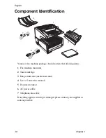
20 Rear Cover
— Remove this cover to expose the expansion slots for
optional memory, ISDN board and network interface card. Use a
Phillips screwdriver to remove screws A and B. DO NOT remove any
other screws. Once you have installed the peripheral equipment,
reattach the rear cover, securing it tightly with screws A and B.
21 AC Power Socket
— Plug the AC power cable supplied with the unit
into this socket.
22 LED Print Head
— This black bar is the transfer mechanism that
writes received/copied information to the image drum. The print head
should be cleaned each time the toner cartridge is changed.
23 Image Drum Unit
— The image drum unit contains a photosensitive
drum (green in colour) which receives information from the LED print
head and transfers it to the printing paper.
24 Toner Cartridge
— This black cylinder, installed on the upper section
of the image drum unit, contains the black powder used as the
machine’s ink for printing data. Install a new toner cartridge when
prompted by a message on the display panel.
Only toner cartridges
specified for use in this machine and available from your authorised
dealer should be installed.)
22
23
24
Содержание OKIFAX 5700
Страница 1: ...User s Guide OKIFAX 5700 5900 PLAIN PAPER FAX...
Страница 10: ...English 1 2 Chapter 1...
Страница 24: ...English 2 2 Chapter 2...
Страница 28: ...English 2 6 Chapter 2...
Страница 90: ...English 6 10 Chapter 6...
Страница 92: ...English 7 2 Chapter 7...
Страница 98: ...English 7 8 Chapter 7...
Страница 100: ...English 8 2 Chapter 8...
Страница 114: ...English 8 16 Chapter 8...
Страница 132: ...English E 4 Appendix E...


