background image

43967002TH  Rev.1 

207 /

Oki  Data  CONFIDENTIAL

4. Part Replacement 

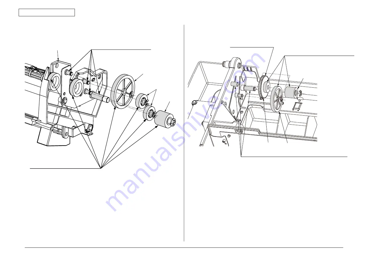
14-3 Guide-Eject-EX-L_Assy

15. Cover-Assy-Top-MFP

Gear-Idle-Z36 

Gear-Idle-Z14S 

Gear-Idle-Z14 

Guide-Eject-EX-L_Assy 

Apply a nomal amount of MOLYKOTE
(EM-30L) to the posts. (4 places.)
EM-30L  Class C

Apply a nomal amount of MOLYKOTE
(EM-30L) to the hatched portions. (6 places.)
EM-30L  Class C

Gear-Knob

Gear-Idle-Z36

Gear-Idle-Z14

Apply a nomal amount of MOLYKOTE
(EM-30L) to the hatched portions.    (3 places.) 
Em-30L  Class C

No grease at the touch part. 

Apply a nomal amount of MOLYKOTE (EM-30L) to the posts. (2 places.) 
EM-30L  Class C

Содержание MC-860 / CX2633MFP

Страница 1: ...MC860 CX2633MFP Maintenance Manual 032007A All instances that mention MC860MFP also apply to the CX2633 unless otherwise noted ...

Страница 2: ... other manufacturers and referred to in this guide will not affect the applicability of the information in it Mention of software products manufactured by other companies does not necessarily constitute endorsement by the manufacturer While all reasonable efforts have been made to make this document as accurate and helpful as possible we make no warranty of any kind expressed or implied as to the ...

Страница 3: ...of this manual can be changed without prior notice There can be errors in this manual even though Oki Data has made best efforts to create the accurate manual Oki Data is not liable for any loss and or damage that are asserted by user to have been caused by the repair adjustment change which are implemented to the MFP by using this manual The parts components that are used in the MFP are delicate ...

Страница 4: ... replacement 83 3 4 5 Duplex unit installation and removal 85 3 5 Report print 88 3 6 Control panel 89 3 7 Menu list 90 3 8 MFP information print 133 3 9 Network information print 134 3 10 Connection method 135 3 10 1 Connect the interface cable 135 3 10 1 1 Connect the network cable 135 3 10 1 2 Connect the USB cable 135 3 10 1 3 Connect the telephone line cable 136 3 10 2 Turn ON the power 139 3...

Страница 5: ...ne For Echo 228 5 8 2 1 TX During send 228 5 8 2 2 RX During receive 229 5 8 3 H Modem Rate 229 5 8 3 1 TX During send 229 5 8 3 2 RX During receive 229 5 8 4 Pulse Make Ratio 230 5 8 5 MF Tome Duration 230 5 8 5 1 ON period 230 5 8 5 2 OFF period 230 5 8 6 Colling Timer 230 5 8 7 Attenuator 230 5 8 8 FM Attenuator 230 5 8 9 Fax maintenance items Default value list 231 5 8 10 Line Test 232 5 8 10 ...

Страница 6: ...normal operations of printer after the power is turned on 318 7 5 2 3 Paper feed jam error 391 1st tray 327 7 5 2 4 Feed jam error code 380 329 7 5 2 5 Paper feed jam error code 390 Multipurpose tray 330 7 5 2 6 Paper running jam error code 381 332 7 5 2 7 Paper running jam error code 382 334 7 5 2 8 Two sided printing jam error code 370 371 372 373 383 336 7 5 2 9 Paper size error error code 400 ...

Страница 7: ...Oki Data CONFIDENTIAL 1 Configuration 1 1 System configuration 8 1 2 MFP configuration 10 1 3 Options configuration 16 1 4 Specifications 18 1 5 Interface specifications 28 ...

Страница 8: ...ASIC B5B Power LVDS I F WAKE UP PCI BUS 5V 24V PRINTER Power Unit Power 5V PCB TB2 LAN IC CIF2 ASIC CC1 ASIC CPU 500MHz NOR FLASH NAND FLASH DRAM 256MB DRAM DIMM 256MB USB Device IEEE 1284 HDD CU FAN PU I F 5V 24V PCB PVM ARMORED ASIC Power FAN 1 Power FAN 2 Duplex Unit PRINTER ENGINE UNIT 2nd Option Tray 3rd Option Tray ASIC ASIC AFE LVDS CCD PCB CCD Motor Driver PCB INVERTER INVERTER LAMP PCB SC...

Страница 9: ...n PCB left Belt unit fuse cut Fuser fuse cut UP LOW upper center Upper side compensation Lower thermistor Low voltage PCB FAN heater control others Fuser entrance release 5V 24V 0VL 0VP AC SW M HEAT Fuser section end cooling FAN Shutter solenoid Low voltage FAN ARMORED CPU PU PCB Fuse cut EXIT Color registration density thermistor signals FLASH 8Mbit Environmental humidity high voltage I F FAN con...

Страница 10: ...43967002TH Rev 1 10 Oki Data CONFIDENTIAL 1 Configuration 1 2 MFP configuration ...

Страница 11: ...ace connector Network interface connector 100 10BASE ACC Parallel interface connector Face up stacker Power connector POWER switch Interface section Duplex unit Ventilation opening Line Tel LINE connector TEL connector Lock release tool Image drum cartridge C cyan blue Image drum cartridge M magenta red Image drum cartridge Y yellow yellow Image drum cartridge K black black Remaining paper indicat...

Страница 12: ...43967002TH Rev 1 12 Oki Data CONFIDENTIAL 1 Configuration Constituent parts and options Duplex unit Paper tray 2 Dedicated table cabinet Paper tray 2 Duplex unit Dedicated table cabinet Paper tray 2 ...

Страница 13: ...on Paper path section Control section CU section PU section SIP section Power supply section High voltage section low voltage section Scanner section Overall configuration of the MC860 is shown in Fig 1 2 Printer section configuration of the MC860 is shown in Fig 1 3 and Fig 1 4 Overall configuration of the scanner section of the MC860 is shown in Fig 1 5 ...

Страница 14: ...43967002TH Rev 1 14 Oki Data CONFIDENTIAL 1 Configuration Fig 1 3 Fig 1 4 ...

Страница 15: ...43967002TH Rev 1 15 Oki Data CONFIDENTIAL 1 Configuration Fig 1 5 ...

Страница 16: ...Data CONFIDENTIAL 1 Configuration 1 3 Options configuration The MFP provides the two types of the add on tray unit and accessories as the options 1 2 stacking tray specifications with short cabinet Model name TRY C3D4 Fig 1 6 ...

Страница 17: ...43967002TH Rev 1 17 Oki Data CONFIDENTIAL 1 Configuration 2 1 stacking tray specifications with long cabinet Model name TRY C3D5 Fig 1 7 ...

Страница 18: ...rage Peak 1300W Category Item Operating environment temperature During operation 10 C to 32 C 17 C to 27 C Full color print quality assurance temperature During non operation 0 C 43 C Power OFF During storage Maximum one year 10 C to 43 C with drum and toners During transportation Maximum one month 30 C 50 C with drum without toners During transportation Maximum one month 30 C to 50 C with drum an...

Страница 19: ...TIAL Oki Data CONFIDENTIAL Category Category Item Item Life Life Toner life Toner life ISO Test Standard ISO Test Standard Starter toner supplied Starter toner supplied Approx 2000 pages black Approx Approx 2000 pages black Approx 2000 pages color 2000 pages color Standard Standard Standard 9 500 pages black 10 000 pages color Standard 9 500 pages black 10 000 pages color S type 2 000 pages black ...

Страница 20: ...sable sizes are different depending on trays Length is up to 1200 mm Minimal paper size Tray 1 A6 A6 Tray 2 option A5 A5 Tray 3 option A5 A5 MPT Postcard Paper thickness Tray 1 64 120 g m2 Tray 2 option 64 175 g m2 Tray 3 option 64 175 g m2 MPT 64 200 g m2 Status switch sensor Paper out Yes Paper low None Toner low Yes Y M C K Cover open Yes Fuser temperature Yes Paper size Yes manual setting Stac...

Страница 21: ...d During ADF scanning Single side 34 pages minute at A4 300 dpi same magnification Warm up time 50 ms or less Life MTBF 5 000 hours or more MTTR Less than 30 minutes Flat bed 5 years or 300 000 times of scan ADF 5 years or 80 000 pages of scan Fluorescent lamp 1 000 hours Light ON accumulative hours Attachment file format PDF JPEG compressed format JPEG JFIF format Multi page format TIFF Non compr...

Страница 22: ...Send Receive memory 16MB Resolution Std 200 x 100dpi Fine 200 x 200dpi Photo 200 x 200dpi ExFine 200 x 400dpi Fax section specifications Item Resolution 600dpi X 600dpi 300dpi X 300dpi Document size Flat bed ODA Tabloid SEF Legal SEF Letter SEF LEF HalfLetter LEF OEL A3 SEF B4 SEF A4 SEF LEF A5 SEF LEF B5 SEF LEF ADF ODA Tabloid SEF Legal SEF Letter SEF LEF HalfLetter LEF OEL A3 SEF B4 SEF A4 SEF ...

Страница 23: ...8 Legal LetterSEF Legal LetterLEF Fit to page 122 Legal Tabloid 129 LetterSEF Tabloid LetterLEF Tabloid HalfLetterLEF LetterLEF HalfLetterLEF LetterSEF 154 HalfLetterLEF Legal Sort ON OFF Item Edge Erase ON OFF print Margin areas A4 destination 5 to 50 mm in units of 1 mm LETTER destination 0 2 to 2 0 inches in units of 0 1 inch Erase Center ON OFF Erase center width A4 destination 1 to 50 mm in u...

Страница 24: ... Letter vertical Half letter horizontal Supported driver TWAIN WIA File format It depends on the scanner application Scan To PC function Item Interface LAN interface connection Communication protocol SMTP POP3 MIME Attachment file format PDF JPEG Compressed M TIFF RAW G3 G4 Compressed JPEG JFIF XPS JPEG XPS cannot be selected in monochrome mode Attachment file format PDF factory shipment default s...

Страница 25: ...cape Messenger4 7 4 73 MAC built in MAIL application Eudora4 3 2J Lotus Notes R5 Item Interface LAN interface connection Supported server CIFS FTP HTTP Attachment file format PDF JPEG Compressed M TIFF RAW G3 G4 Compressed JPEG JFIF XPS JPEG XPS cannot be selected in monochrome mode Attachment file format PDF factory shipment default setting Default setting can be changed Resolution 75 100 150 200...

Страница 26: ...witched Telephone Network PBX Interface LINE 1 TEL 1 built in telephone option One touch dial None Speed dial Supported 500 destinations Speed dial search Supported Search is possible form each tab of Destination table List Group In the order of number Reading and Symbol Group Supported Maximum 32 groups Real time transmission Yes Memory transmission Yes Transmission at the specified time includin...

Страница 27: ... IEEE802 1X Supported SNMP V3 Supported SSL TLS Supported IPSec Supported IP filtering Supported MAC filtering Supported Item PIN access control Access control to Copy Print Scan To functions and Fax send is possible by the PIN ID of 1 to 10 digits Item Job accounting utilities Accounting by PIN ID Some functions are restricted Account log Number of user IDs that can be registered 5000 IDs Number ...

Страница 28: ...interface specifications Fundamental specifications Network protocol TCP IP related NetWare related Ether Talk related NetBEUI related Connector 100 BASE TX 10 BASE T Automatic switching Simultaneous use is not possible Cable Non shielded twist pair cable with RJ 45 connector Category 5 is recommended Connector pin arrangement Interface signal Pin No Signal name Direction Function 1 TxD FROM PRINT...

Страница 29: ...rface signal Pin No Signal name Direction Function 1 nStrobe HostClk TO PRINTER Pulse to read data Data is read at trailing edge 2 9 DATA 1 DATA 8 Bi direction 8 bit parallel data High level is 1 and low level is 0 10 nAck PtrClk FROM PRINTER Signal indicating completion of data reception 11 Busy PtrBusy FROM PRINTER Signal indicating if a printer is ready to receive data Data reception is impossi...

Страница 30: ...Oki Data CONFIDENTIAL 2 Theory of Operation 2 1 Electro photographic process system 31 2 2 Print process 34 2 3 Image scanning process 44 ...

Страница 31: ...rred to a paper when electric charge is applied to the transfer roller from the back of a paper 5 Drum cleaning The drum cleaning blade removes the residual toner that is remained on the OPC drum after image transfer 6 Belt cleaning The belt cleaning blade removes the residual toner that is remained on the belt 7 Fix Toner is fused when heat and pressure applied to the toner image on the print pap...

Страница 32: ...ualized by toner 5 Transfer Print paper is overlaid on the OPC drum surface and charge is provided by the transfer roller from the back side of the paper When a high voltage is applied to the transfer roller the charge that is induced on the transfer roller is transferred to the paper surface at the contacting point between the transfer roller and paper Thus the toner is attracted on the paper sur...

Страница 33: ...contacting with the backup roller surface For safety purpose thermostat is provide If the heat roller temperature increases higher than the specified temperature the thermostat opens so that the voltage supply to the heat is shut down The backup roller unit is pressed against the heater by the pressure springs on both sides 7 Drum cleaning The toner that is not used for fusing and remained on the ...

Страница 34: ...per path of the Duplex unit so that the paper enters the same paper transport path as the feed paper route from the trays The remaining operations are the same as those of the one sided print using the paper supplied from the trays Face down stacker Face up stacker MPT Paper inverting transport path Sub roller Feed roller Sub roller Transport roller Feed roller Regist roller L Regist roller U MPT ...

Страница 35: ...d amount of paper is transported so that the paper is pressed against the regist roller U Thus paper skew is corrected 3 The regist motor rotates in counter clockwise direction as shown in Fig 2 4 the paper is transported by the regist roller U When the regist motor rotates in counter clockwise direction the regist roller U is activated Fig 2 3 Fig 2 4 3 Transport belt 1 When the transport belt mo...

Страница 36: ...e print are shown in Fig 2 7 When the lift up motor rotates in clockwise direction the lift up link slide to the right and moves down the respective ID units as shown in Fig 2 7 This condition means that monochrome print is ready Lift up link C ID unit M ID unit Y ID unit K ID unit Lift up motor Rotates in counter clockwise direction Operations of the respective ID units during color print C ID un...

Страница 37: ... the covers of the color registration error sensor and of the density sensor 1 When the solenoid activated to ON as shown in Fig 2 9 the link lever is moved to open the covers of the color registration error sensor and of the density sensor 2 When the solenoid is deactivated to OFF the spring presses the covers so that the covers of the color registration error sensor and of the density sensor are...

Страница 38: ...short time When printing of more than 400 sheets is executed after the previous color registration error correction The correction error can occur depending on the amount of toner of the generated pattern or due to the dirty sensor stained by toner or because of the defective operation of the shutter open close operations However because the error is not displayed on the operator panel even when t...

Страница 39: ...ensor PCB PRC PCB relay PCB P6Y PCB PU PCB PU PCB and the connection cables one after another with the good one to locate the cause of the error Check that the error does not occur when each PCB is replaced BELT REFLX ERR Check 4 When this error display appears check the cleaning status of the toner that has remained on the belt surface in addition to the above checks 1 2 and 3 Remove the belt uni...

Страница 40: ...ection error can occur depending on the amount of toner of the generated pattern or due to the dirty sensor stained by toner or because of the defective operation of the shutter open close operations However because the error is not displayed on the operator panel even when the error occurs the error display should be checked by implementing the density error correction forcibly by using the self ...

Страница 41: ...ion of toner At the same time ID contains the shutter The shutter operates in synchronism with the operation lever of the toner cartridge and can detect whether the toner cartridge is normally installed by using the toner sensor If the light shielding plate or the toner sensor becomes dirty by the toner of the ID unit faces against the toner sensor in the specified location due to the defective in...

Страница 42: ...ount is not executed during the feed paper hopping jam and feed jam 380 Jams other than those are counted Because the total number of printed sheets are counted when top end of paper has passed the write sensor the feed jam 380 is included in the condition of not counting the jam if jams are classified by the jam types When jam occurs before paper passes the fuser unit the jam is not counted Jams ...

Страница 43: ...ABLOIDEXTRA 2 4 TABLOID 2 4 A3 NOBI 2 4 A3 WIDE 2 4 A3 2 4 A4 1 2 A5 1 2 A6 1 2 B4 2 4 B5 1 2 COM 9 1 2 COM 10 1 2 MONARCH 1 2 DL 1 2 C5 1 2 C4 1 2 HAGAKI 1 2 OUFUKU HAGAKI 1 2 Paper size Simplex Duplex CUSTOM 1 2 CUSTOM LENGTH 210mm 2 4 ENVELOPE1 Choukei 3 1 2 ENVELOPE2 Choukei 4 1 2 ENVELOPE3 Youkei 4 1 2 ENVELOPE4 Envelope A4 1 2 ENVELOPE5 Kakugata 2 2 4 ENVELOPE6 Kakugata 3 1 2 ENVELOPE7 Kakug...

Страница 44: ... configuration Electrical control of the MFP is executed by the reader controller circuit PCB and the image processor circuit PCB The ASIC of the reader controller circuit PCB and the ASIC of the image processor circuit PCB interpret the input signals that are supplied from sensors and the signals that are supplied from the externally connected equipment The ASICs output the signals that drive the...

Страница 45: ...ve operation modes are executed in accordance with the instructions given by the connected equipment to implement the print operation Name of the operation modes the overview of the operation and the corresponding print modes are shown in the following table Name of the operation modes Overview of the operation Supporting print modes 1 Normal direction feed paper Unload paper Document is fed and s...

Страница 46: ... flow is shown below Supplement When a both sided document is selected this operation is performed regardless of the same size mixed documents or different sizes mixed documents Document Feed paper Loop creation Scanning Transport Inversion Scanning standby Loop creation Scanning standby Rear side scanning Transport Transport Inversion Preliminary feeding Unload paper Transport Job end ...

Страница 47: ... sensor PI3 and the document set sensor PI11 detect if the document that has started scanning is the final document or not If the final document is fed and the rear end of the final document has passed the final document detection lever of the document tray the detection lever moves together with the light shielding plate so that the photo interrupter that has been shutting down the light passes t...

Страница 48: ...ht into the two document width sensors inside the document tray is interrupted by the light shielding plate that is installed in the lower part of the slide guide The document size is identified by the combination of the ON OFF signal from the document length sensors and the ON OFF signal from the document width sensors Relationship between the respective length detection sensor signals the docume...

Страница 49: ...d equipment memorizes the contents of the jam as a jam code The jam code of the MFP can be checked by outputting the jam error history report by the service mode of the connected equipment 2 3 1 6 Power supply Power supply Overview of the power supply is shown in the illustration below The power supply block of the MFP receives the power supply of two systems that are 24 V power supply and 3 3 V p...

Страница 50: ...of the carriage A The light irradiated by the cold cathode tube enters the carriage A carriage B lens in this order and reaches the CCD device The optimal focal length is maintained by the scanning that maintains a specified distance between the carriage A and the carriage B 2 3 2 2 Exposure block 1 Reflect tape The document such as book does not contact completely with the glass surface Therefore...

Страница 51: ... carriage A is the position where the home sensor is located The home sensor position is the reference position of the scanning operation Carriage B The mirrors B and C are fixed to the holder with the relative angle of 90 degrees The reflected light from the mirror A is input to the CCD device via the mirrors B and C and lens The mirror carriage B is driven by the FBS motor using a timing belt an...

Страница 52: ...ht to document and the light is detected by CCD device In the vertical scanning direction the beam sensor receives the reflected light from document and the document size detection is executed Document size beam sensor vertical direction CCD horizontal direction Document size Beam sensor vertical direction CCD horizontal direction A4 A4 A5 A5 B4 B5 B5 A3 Detection ...

Страница 53: ...Installation of MFP 55 3 3 Installation of add on tray unit 64 3 4 Preparation before use 77 3 5 Report print 88 3 6 Control panel 89 3 7 Menu list 90 3 8 MFP information print 133 3 9 Network information print 134 3 10 Connection method 135 3 11 Checking papers used by user 140 ...

Страница 54: ...hot that can cause fire If the cover gets abnormally hot or the printer smokes or smells strange odor or generates abnormal sound disconnect the AC power plug from the power supply source and contact Oki contact point Failure to observe the caution may result in fire Warning If liquid such as water gets inside of the printer disconnect the AC power plug from the power supply source and contact Oki...

Страница 55: ...llowing precautions may result in physical damage The MFP is heavy weighing approx 68 kg Three or more persons should work together to raise the MFP Remove the four handles from sides of the cardboard box as shown in the illustration and raise the cardboard box Handle at four locations on the sides 3 2 1 Unpacking ...

Страница 56: ...ve the following precautions may result in physical damage The MC860dn is heavy weighing approx 68 kg Three or more persons should work together to raise the MFP MC860 main unit Note The image drum cartridges have alredy been installed inside the main unit earlier Software CD ROM 2 pieces Memo The add on tray unit 1 stacking tray with long cabinet and 2 stacking tray with short cabinet can be inst...

Страница 57: ...pare a printer cable separately in accordance with the PC to be connected The carton box and cushions are re used in future for transportation Do not discard them but keep them Use the telephone cable supplied If the 4 conductor telephone cable is used communication cannot be established Cable Cap 2 pieces Cover Lock release tool Cord guide Cord clamp 2 pieces Cover plate large 2 pieces Cover plat...

Страница 58: ...H relative humidity Maximum wet bulb temperature 25 C Be careful that there should not be any dew condensation If the MFB is going to be installed in the locations where ambient humidity is less than 30 use humidifier or anti static mat Installation space Place the printer on a flat table that has the sufficient space to accommo date all of the printer feet Secure sufficient space around the print...

Страница 59: ...n tape Protection tape Cushion material Cushion material Vinyl bag Instruction Sheet Take the main unit out from the carton box and remove the Instruction Sheet and cushions Note Be sure to hold the main unit by three or more people Peel off the protection tape from the back and side of the main unit Pull the cover open lever and open the document cover Open the sub cover and remove the protection...

Страница 60: ...ocument cover Raise the document table cover Remove the protection material and the protection sheet Instruction Sheet Document table lock lever Document table Return the document table cover to the original position Document table cover Pull the document table lock lever to the front and raise the document table Remove the Instruction Sheet ...

Страница 61: ...ion tape desiccating agent Remove the protection sheet and desiccating agent Return the document table cover to the original position Close the MP tray MP tray Protection sheet Hold both ends of the MP tray and open it to the front Remove the protection sheet MP tray Document table ...

Страница 62: ...button and open the top cover Do not hold the image drum cartridge with a single hand Remove the image drum cartridges 4 pieces gently with both hands Note The image drum green tubular portion is highly inherently brittle Be very careful when handling it Be very careful not to expose the image drum to direct sun light or intense light light of approx 1500 lux or more Do not leave it under the norm...

Страница 63: ...e Replace the toner check if the toner cartridge lever is fully pressed in the direction of the arrow up to the end 3 Release the lock Two screws Lock release tool Turn the two screws on the side panel in the direction of the arrow with the lock release tool supply to release the lock Lock release tool Install the lock release tool on the back of the main unit ...

Страница 64: ...ilure to observe the following precautions may result in physical damage The MFP is heavy weighing approx 68 kg Three or more persons should work together to raise the MFP Remove the four handles from sides of the cardboard box as shown in the illustration and raise the cardboard box Handle at four locations on the sides ...

Страница 65: ...continuously with the standard paper tray and the MP tray The add on trays are available as options in MC860dn Note A6 size paper cannot be used Memo The add on trays are sometimes called tray 2 and tray 3 Add on tray unit Accessories 2 stagger tray with short cabinet Model name TRY C3D4 Fastener 4 pieces Side cover left Fall prevention foot covers 6 pieces Fall prevention foot rear 2 pieces Fall ...

Страница 66: ...43967002TH Rev 1 66 Oki Data CONFIDENTIAL 3 Installation 3 3 3 Installation method Top view MC860dtn Side view MC860dtn 60cm 20cm 20cm 100cm 60cm ...

Страница 67: ...y two or more people 2 Turn OFF the power of the main unit and remove the power cord and cables Note If the add on tray unit is installed with the main unit power ON the main unit may be damaged Memo For the method of turning OFF the power refer to page xx gTurn OFF the power h of the User fs Manual Basic Operation edition 3 Attach the fall prevention foot Fix the fall prevention foot front to the...

Страница 68: ...stall the main unit on top of the add on tray unit Align the holes on the bottom of the main unit with the three protrusions of the add on tray unit Install the main unit on top of the add on tray unit gently Caution Failure to observe the following precautions may result in physical damage The MC860dn is heavy weighing approx 68 kg Three or more persons should work together to raise the MFP Hole ...

Страница 69: ...ghten these screws with force Align the lower hole of the fastener with the screw hole of the add on tray unit Insert the screw and tighten the screw lightly Note Do not tighten with force Screw Hole Add on tray unit Screw hole Main unit Fastener Insert the fastener into the installation position from the front on the left side of the main unit Fixing screw Stud Fixing screw Stud Left side Right s...

Страница 70: ...Screw hole Screw Two screws Tighten the two screws at the front on the right side by performing steps and Fastener Two screws Align the upper hole of the fastener with the screw hole of the main unit Insert the screw from the bottom and tighten it lightly Insert the fastener into the installation position from the front on the left side of the main unit ...

Страница 71: ...ay unit tightly Tighten securely the 8 screws that were loosened in step 5 and 0 8 screws that were tightened only temporarily in step 5 totaling 16 screws with force Left side Screw Screw Screw Screw Screw Screw Screw Screw Tighten the two screws at the deep end on the right side by performing steps and ...

Страница 72: ... Prepare the side cover left Hole Hole Hook Side cover left Add on unit Protrusion Right side Screw Screw Screw Screw Screw Screw Screw Screw Insert the hook of the side cover left into the lower hole of the add on tray unit and press the hook against the add on unit to install it ...

Страница 73: ...er right Attach the side cover right in the same procedure as and 8 Attach the fall prevention foot Add on unit Hole Hole Hook Protrusion Side cover right Cover Cover Confirm that the side cover is installed securely Attach the covers at 6 locations to the fall prevention foot Confirm that the side covers are installed securely ...

Страница 74: ... to Chapters 3 to 8 and perform the following setups Note You must log on with administrator authority For the Windows PS printer driver For Windows Vista Server 2008 select the menus Start Control Panel Printers For Windows select menus Start Control Panel Printers and Other Hardware Printers and Faxes For Windows Server select the menus Start Printers and Faxes For Windows 2000 select the menus ...

Страница 75: ... number of trays at present in the Usable Devices Click OK For Mac OS X For Mac OS X if an option has been added before the printer driver is installed the device information is obtained automatically However if connection is made via IP Print or Bon jour Rendezvous the device information cannot be obtained automatically When Apple Talk is used for connection if option is added after the printer d...

Страница 76: ...10 5 is used Select the hard disk menus Application Utilities and double lick Printer setup utilities Select MC860 and click View information and open Printer information Select Installation Options Select an appropriate value from Number of tras and click Apply change Close Printer Information ...

Страница 77: ... A6 size paper move the paper stopper to the front and remove it Then attach it in the position shown Note Set papers so that paper should not exceed the down triangle mark 300 sheets with realm weight 70 kg paper Face the printing side down Down triangle mark Direction of setting paper B5 Letter Set the papers with printing side facing down to the front of the paper cassette Fan the papers well a...

Страница 78: ...ation Paper size dial Reference For details refer to Paper size dial page Adjust the paper size dial in accordance with size of the set paper Direction of the set paper and symbol of the paper size dial should match Return the paper cassette to the MFP ...

Страница 79: ... damaged power cord Do not connect many loads on one electrical outlet Do not share the same electrical outlet with other electric products If air conditioner copying machine paper shredder are connected in parallel the MFP may malfunction due to electric noise If the MFP shares the same electrical outlet with other electric products use the noise filter or noise cut transformer that is available ...

Страница 80: ...ss Yes 4 When the following screen is displayed turn OFF the POWER switch When the MFP is not gong to be used for long time Explain to users to disconnect the power cord when the MFP is not gong to be used for long time due to vacation or trip Note This MFP will not cause any functional trouble even when the power plug is kept disconnected for long period of time 4 weeks or longer Explain to clien...

Страница 81: ...ables Note If add on memory is installed while the power is ON it can cause damage of the MFP and add on memory Do not touch electronic part and connector terminal Be careful for the correct direction of the add on memory Terminal of memory chip has the index cut out so that memory chip fits the slot connector Memo For the method of turning OFF the power refer to page 22 Turn OFF the power of the ...

Страница 82: ...lant the memory toward the MFP side and fix it Check that the cable white on the left of the memory is not disconnected from the connector Close the sub cover door Press View Information Check the Total Memory Note If the Total Memory is not displayed correctly re install the memory 4 Connect the AC power cord and cables Turn ON the power 5 Check that the add on memory is installed normally Press ...

Страница 83: ...isk for IC card certification supporting the group print function supplied with the card certification kit F10 Printing from a specific printer among a group of printers is possible by touching the IC card with the IC card reader that is connected to the desired printer For details refer to the Manual supplied with the card certification kit F10 Any one type of hard disk among the three types can ...

Страница 84: ...procedure of item 3 5 Confirm that the internal HDD capacity is displayed in HDD Memo Capacity of HDD can be different from the example show in the illustration Note If the memory capacity is not displayed correctly re install the HDD Note When the internal HDD for the IC card certification is going to be installed read the Manual supplied with the HDD beforehand 4 Perform the menu map print to co...

Страница 85: ... the item 3 5 2 Turn OFF the power Note If the duplex unit is installed with the MFP power ON the MFP may be damaged O I Duplex unit 穴 Claw 2 Install the duplex unit Insert the duplex unit securely into the deep end in the bottom on the back of the MFP Confirm that the claws at both ends of the duplex unit are inserted into the printer holes securely 3 Connect the AC power cord and printer cable t...

Страница 86: ...etups For those who use Windows PS printer driver Open the file that you want to print Select the File menu and Print Click Detailed setting This operation is not required in Windows 2000 Select the Layout tab Both side print Binding long side Execute print For those who use Windows PCL PCL XPS Open the file that you want to print Select the File menu and Print Click Detailed setting This operatio...

Страница 87: ... Select the File menu and Print Select the Layout panel Both side print Binding long side or Binding short side Execute print Memo If Printer option is not displayed in the Print dialog box in Mac OS X 10 5 click the downward triangle XXX button that is located next to the Printers pop up menu Mac OS X 10 5 PS Printer driver ...

Страница 88: ... address MAC address and others or the remaining amount of consumable items or whether the printer section of this MFP is working normally or not they are printed by this print How to print 1 Press the REPORTS key Example of print result 2 Press MFP Setup 3 The confirmation screen is displayed Press Yes Reference For other report prints refer to the User s Manual Advanced edition ...

Страница 89: ...g or to indicate number of copies 4 SETUP key This key is pressed to call a specific function 13 FA JOB VIEW CANCEL key Communication can be checked or stopped 5 REPORT key This key is pressed to output the various reports 14 POWER SAVE key This key is pressed to enter the Power save mode to reduce power consumption during standby page 19 6 JOB PROGRAMS key This key is pressed to register the Job ...

Страница 90: ... ON OFF Set Enable Disable binding margin Left Front 0 25mm 1mm Step 0 0 1 0inch 0 1inch Step Set distance of movement of copied output image toward right on the front side of copy paper Display in units of mm or display in units of inch can be switched by changing the unit of display on the system setup Top Front 0 25mm 1mm Step 0 0 1 0inch 0 1inch Step Set distance of movement of copied output i...

Страница 91: ...inch 0 1inch Step Set erasing width when erasing frame Display in units of mm or display in units of inch can be switched by changing the unit of display on the system setup Erase Center Erase Center ON OFF Set default setup of selection whether to erase or not shade that is created in the center of two page spread document Erase Width 1 50mm 1mm Step 0 1 2 0inch 0 1inch Step Set erasing width whe...

Страница 92: ...up Removal for Background Show Through sTHR Auto OFF 1 2 3 4 5 sTHR Set default setup of selection whether the background color of document and offset phenomenon becomes less significant or not Density 3 2 1 0 1 2 3 Set image density The shaded portion shows the default setup value when shipped from the factory Item Contents Tray Auto MP tray Tray 1 Tray 2 Tray 3 Select a document feeding tray Zoo...

Страница 93: ...FF Set whether or not to print result of transmission automatically Deleyed Tx Date hour minute Send transmission by specifying time The shaded portion shows the default setup value when shipped from the factory Item Contents others Polling ON OFF Set whether or not to set up polling reception F Polling Sub address Set sub address Password Set password F Code Tx Sub address Set sub address Passwor...

Страница 94: ...density when scanning document TTI ON OFF Set whether or not to print sender s name on document when it is printed at destination TTI Select 1 2 3 Select name of sender Names of sender as many as three can be registered by MPF Setup Administrator Setup Installation Mode MCF Report ON OFF Set whether or not to print result of transmission automatically Register prefix number PreFix 001 100 Prefix n...

Страница 95: ...selected from address book and from LDAP by calling destination E mail Subject Subject Enter subject Maximum 80 characters with half sized character or 40 characters with full size can be registered Text fixed phrase Enter body text Maximum 256 characters with half sized character or 128 characters with full size can be registered New Subject Enter new subject Select Subject Select it from the alr...

Страница 96: ... scanning in B W with grayscale being set to ON Mono Binary High G4 Medium G3 Raw Set compression rate when scanning in B W with grayscale being set to OFF Edge Erase Edge Erase OFF ON Set default setup of selection whether to erase or not shade that is created in the surrounding of two page spread document The shaded portion shows the default setup value when shipped from the factory Item Content...

Страница 97: ...to be made by use name on this screen When the Detail button is pressed the detail search can be used in which search is made by specifying the search method AND OR user name and E mail address for searching The addresses that are selected as destination can be imported to local address book 100 search results can be displayed Doc Type Doc Type Text Text Photo Photo Select image quality when scann...

Страница 98: ... compression rate for scanning Mono Grayscale High Medium Low Set compression rate when scanning in B W with grayscale being set to ON The shaded portion shows the default setup value when shipped from the factory Item Contents others ComprsRt Mono Binary High G4 Medium G3 Raw Set compression rate when scanning in B W with grayscale being set to OFF Edge Erase Edge Erase OFF ON Set default setup o...

Страница 99: ...selection whether the background color of document and offset phenomenon becomes less significant or not Density 3 2 1 0 1 2 3 Set density when scanning document The shaded portion shows the default setup value when shipped from the factory Item Contents Resolution 75 dpi 100 dpi 150 dpi 200 dpi 300 dpi 400 dpi 600 dpi Select resolution when scanning document Scan Size Auto Letter Letter Tabloid L...

Страница 100: ...n creating sub folder Duplex Scan OFF Right Left Top Set binding position of document Cont Scan OFF ON Select to inquire or not to inquire if next page of document is ready Direction Left Edge Top Edge Set orientation of document that is set on glass and set orientation of image Left end Starting origin of horizontal scanning is set to the left end of image Top end Starting origin of horizontal sc...

Страница 101: ...anging the unit of display on the system setup EraseCenter Erase Center OFF ON Set default setup of selection whether to erase or not shade that is created in the center of two page spread document Erase Width 1 50mm 1mm Step 0 1 2 0inch 0 1inch Step Set erasing width when erasing center Display in units of mm or display in units of inch can be switched by changing the unit of display on the syste...

Страница 102: ... Delete the encryption job Job Lists 100 jobs are displayed in the order of priority A job can be aborted by selecting a job The shaded portion shows the default setup value when shipped from the factory Item Contents Density 3 2 1 0 1 2 3 Set density when scanning document Resolution 75 dpi 100 dpi 150 dpi 200 dpi 300 dpi 400 dpi 600 dpi Select resolution when scanning document Scan Size Auto Let...

Страница 103: ... sized character or 8 characters with full size can be registered E mail address Enter E mail address 80 characters in half size alphanumeric characters can be registered Group number Select group Delete Delete the address Delete and Sort Delete address and roll up in order Insert Input the address Group Name Set name of group Maximum 16 characters with half sized character or 8 characters with fu...

Страница 104: ...is selected as paper size Display in units of mm or display in units of inch can be switched by changing the unit of display on the system setup 4 1 inch 8 3 inch 11 7 inch Length 148 mm 297 mm 431 mm It can be set only when Custom is selected as paper size Display in units of mm or display in units of inch can be switched by changing the unit of display on the system setup 5 8 inch 11 0 inch 17 0...

Страница 105: ... a paper size The shaded portion shows the default setup value when shipped from the factory Item Contents Tray 3 Custom Width 148 mm 210 mm 297 mm It can be set only when Custom is selected as paper size Display in units of mm or display in units of inch can be switched by changing the unit of display on the system setup 5 8 inch 11 0 inch 17 0 inch Length 182 mm 297 mm 431 mm It can be set only ...

Страница 106: ...0 mm 297 mm It can be set only when Custom is selected as paper size Display in units of mm or display in units of inch can be switched by changing the unit of display on the system setup 2 5 inch 8 3 inch 11 7 inch Length 105 mm 297 mm 1200 mm It can be set only when Custom is selected as paper size Display in units of mm or display in units of inch can be switched by changing the unit of display...

Страница 107: ... setup value when shipped from the factory Item Contents Register Edit Profile Name Enter name of profile Maximum 16 characters with half sized character or 8 characters with full size can be registered Protocol CIFS FTP HTTP Select protocol to be used for storing file Target URL Specify server address and directory to store the scanned data Maximum 144 characters with half sized character or 72 c...

Страница 108: ...strator setting menu Resolution 75 dpi 100 dpi 150 dpi 200 dpi 300 dpi 400 dpi 600 dpi Select resolution when scanning document The default value is what is specified by the Administrator setting menu The shaded portion shows the default setup value when shipped from the factory The shaded portion shows the default setup value when shipped from the factory Item Contents Register Edit Scan Size Aut...

Страница 109: ...ator setting menu Display in units of mm or display in units of inch can be switched by changing the unit of display on the system setup Erase Center Erase Center OFF ON Set default setup of selection whether to erase or not shade that is created in the center of two page spread document The default value is what is specified by the Administrator setting menu Erase Width 1 50mm 1mm Step 0 1 2 0inc...

Страница 110: ...x xxxxxxxxxxxxx Indicates serial number 26 alphanumeric character at a maximum Asset No xxxxxxxx Indicates asset number 8 alphanumeric character at a maximum Lot No xxxxxxxxxxxxx xxxxxxxxxxxxx Indicates production lot number 26 alphanumeric character at a maximum CU Version xx xx Indicates version number of CU Control Unit firmware PU Version xx xx xx Indicates version number of PU Print Unit firm...

Страница 111: ...ult setup to sort copied sheets in the order of page number Select the default setup whether documents of different sizes are copied to the papers of different sizes or not Margin Margin OFF ON Set default setup of Enable Disable binding margin Left Front 0 25mm 1mm step 0 0 1 0inch 0 1inch step Set default setup of distance of movement of copied output image toward right on the front side of copy...

Страница 112: ...nch 0 1inch step Set default setup of erasing width when erasing center Display in units of mm or display in units of inch can be switched by changing the unit of display on the system setup Duplex Copy CopyMethod OFF 1 2 sides 2 2 sides 2 1 side Set default setup of selecting type of both sided copying Binding Right Left Top Set the default setup of binding position of document Mixed Size OFF ON ...

Страница 113: ...shipped from the factory Item Contents F code Box Register Edit Secure Box Name of box Enter name of confidential document box Sub Address Enter name of confidential document box More than 1 character and maximum 20 characters 0 to 9 Numeral only Password Enter name of confidential document box More than 1 character and maximum 20 characters 0 9 Numeral only Retention period 00 to 31 days Security...

Страница 114: ...le pressing of dial Auto Print Journal Report Setting OFF ON Set automatic printing of communication result report Print time OFF ON Enter day and time to specify The shaded portion shows the default setup value when shipped from the factory Item Contents Other Settings Redial Trise 0 Times 3 Times 14 Times Set number of times of redialing Redial Interval 0 Min 1 Min 5 Min Set interval between red...

Страница 115: ... 4 5 sTHR Set default setup of background offset phenomenon removal Density 3 2 1 0 1 2 3 Set default setup of density The shaded portion shows the default setup value when shipped from the factory Item Contents Default Settings Common to Scan To E mail and Scan To USB memory Resolution 75 dpi 100 dpi 150 dpi 200 dpi 300 dpi 400 dpi 600 dpi Set default setup of resolution Scan Size Auto Letter Let...

Страница 116: ...mpression rate when scanning in B W with grayscale being set to OFF EdgeErase Edge Erase OFF ON Set default setup whether or not to erase shade that is created in the surrounding area of two page spread document Width 5 50mm 1mm step 0 2 2 0inch 0 1inch step Set default setup of erasing width when erasing frame Display in units of mm or display in units of inch can be switched by changing the unit...

Страница 117: ... a paper feeding tray Tray 2 3 are indicated only when it is installed Auto Tray Switch OFF ON Set the automatic switching of trays Tray Sequence Down Up Paper FeedTray Specify priority when selecting order at the automatic tray selection automatic tray switching The shaded portion shows the default setup value when shipped from the factory Item Contents Print Menu Tray Configuration MP Tray Usagc...

Страница 118: ...onds Set the time to wait before paper is set during the manual feeding mode Wait Timeout Disable 5 seconds 10 seconds 20 seconds 30 seconds 40 seconds 50 seconds 60 seconds 90 seconds 120 seconds 150 seconds 180 seconds 210 seconds 240 seconds 270 seconds 300 seconds Set the time before starting the forced printing after data is no more received PS cancels the job Low Toner Stop Continue Set whet...

Страница 119: ...g vertical direction along with the paper running direction Back X Adjust 0 2 00 mm 0 25mm Step Corrects position of the entire print image in the direction of running vertical direction along with the paper running direction during rear side printing of both side print Back Y Adjust 0 2 00 mm 0 25mm Step Corrects position of the entire print image in the direction of running vertical direction al...

Страница 120: ...inting to darker and pressing toward minus changes printing to thinner Yellow MID TONE 3 2 1 0 1 2 3 Adjusts color tone at mid tone portion of yellow The shaded portion shows the default setup value when shipped from the factory Item Contents Color Menu Yellow DARK 3 2 1 0 1 2 3 Adjusts color tone at dark portion of yellow Black HIGHLIGHT 3 2 1 0 1 2 3 Adjusts color tone at thin Highlight portion ...

Страница 121: ...hen shipped from the factory Item Contents Color menu Yellow Reg Fine Adj 3 2 1 0 1 2 3 Finely adjusts the image position error of yellow Ink Simulation OFF SWOP EUROSCALE JAPAN Sets the ink simulation This setup is valid only for the PS language job UCR Low Medium High Enables selection of amount of black ink Black during color printing Increasing amount of black ink economizes amount of toner of...

Страница 122: ...termines if MFP recovers automatically when memory overflow occurs Error Report OFF ON This setup determines if error report is printed or not when postscript error occurs PCL Setup Font Source Resident Specify location of fonts to use Font No I0 I90 Select number of font to use When Internal fonts is selected a value in the range of I0 I90 is selected Font Pitch 0 44 CPI 10 00 CPI 99 99 CPI Sets ...

Страница 123: ... line feed on A4 paper White Page Skip OFF ON It sets whether to print blank white page or not CR Function CR CR LF Set the MFP operation when receiving CR code LF CR Function LF LF CR Set the MFP operation when receiving LF code Print Margin Normal 1 5 inch 1 6 inch Sets the unprintable area on paper Make correction in the way so that thin green becomes visible True Black OFF ON Sets whether blac...

Страница 124: ...CP IP is invalid or if IP version number is IPv6 IPv4 address 100 It sets IP address This menu is not displayed when TCP IP is invalid or if IP version number is IPv6 The shaded portion shows the default setup value when shipped from the factory Item Contents Network setup Subnet Mask It sets subnet mask This menu is not displayed when TCP IP is invalid or if IP version number is IPv6 Gateway Addr...

Страница 125: ... default setup value when shipped from the factory Item Contents Mail Server Setup SMTP Server IP address or name of server Sets IP address of SMTP server or sets name of server SMTP Port 1 25 65535 Set port number of SMTP server Use the default setup normally SMTP Encryption None SMTPS STARTTLS Set encryption of communication with mail server SMTP POP3 Server IP address or name of server Sets IP ...

Страница 126: ...Name search condition 2 Specify attribute that is used for searching name Default setup is cn Name 3 Name search condition 3 Specify attribute that is used for searching name Default setup is givenName E mail Address E mail address search condition Specify attribute that is used for searching E mail address Default setup is mail The shaded portion shows the default setup value when shipped from th...

Страница 127: ...t are displayed on the favorite switch items on the Scanner standby screen E mail The following items can be set Reply to E mail edit File Name Duplex Scan Cont Scan Direction Grayscale File Format Comprs Rt Frame erase Erase Center Contrast Hue Saturation RGB Logout 2 Doc Type 3 Density 4 Resolution 5 Scan Size The shaded portion shows the default setup value when shipped from the factory Item Co...

Страница 128: ...Type 3 Set tone when flatbed scanning is completed Paper Jam Alert OFF ON Select ON to sound paper jam alarm The shaded portion shows the default setup value when shipped from the factory Item Contents Auto Reset Time Scanner Screen Reset time 1 minute 5 minute 10 minute Sets time of automatic reset Reset After Scan OFF ON Set screen reset upon completion of scanning Sound Setup Volume OFF Low Mid...

Страница 129: ...nal Parallel PS Protocol ASCII RAW CENTRO USB PS protocol Offline Receive Disable Enable Set whether to receive data in offline state or in recoverable error state The shaded portion shows the default setup value when shipped from the factory Item Contents System Setup Access Control PIN User Password Disable Set access control User Auth Method Local LDAP SecureProtocol It is displayed when User P...

Страница 130: ...MB 32MB Set receive buffer size that the local interface secures Resource save area Auto OFF 0 5 MB 1 MB 2 MB 4 MB 8 MB 16 MB 32MB Set the resource save area Flash Memory Setup Initialization Execute Initialize the Flash memory Delete the registered Demo data HDD Setup Initialization Execute Initialize hard disk Demo data and print job are deleted Format PCL Common PS Format hard disk Demo data an...

Страница 131: ...History information are deleted Various setups are returned to default setups Job Log Clear Execute Delete the encryption job The shaded portion shows the default setup value when shipped from the factory Item Contents Time Setup Setting time Set time Set Daylight Saving OFF ON Setting ON OFF of Daylight save made Time Zone 0 00 Sets time difference from GMT Comm Line Push Dial 10 Dial 20 Select t...

Страница 132: ... for transmission Mirror Carriage Mode Execute When Yes is selected it moves the mirror carriage to the transfer mode position Erase Privacy Data Execute This setup deletes the registration data job logs and logs such as E mail address and abbr dial and returns these setups to the default setups It takes 2 to 3 hours Do not turn OFF the power during progress When Job Programs Setting is pressed It...

Страница 133: ...67002TH Rev 1 133 Oki Data CONFIDENTIAL 3 Installation 3 8 MFP information print Sample Confirm that the MFP works normally 1 Set A4 paper in the tray 2 Press REPORTS key 3 Press Configuration 4 Press Yes ...

Страница 134: ...TIAL 3 Installation Sample 3 9 Network information print Check the Network information print 1 Press the TEST switch near the Network connector on the back of MFP for 5 seconds and release hand from the switch Network information is printed ...

Страница 135: ...twork 3 10 1 Connect the interface cable 3 10 1 1 Connect the network cable 3 10 1 2 Connect the USB cable 1 Prepare a USB cable Note USB cable is not supplied Prepare cable of USB2 0 specification separately When connecting with the USB 2 0 Hi Speed mode prepare a USB cable supporting Hi Speed specifications USB interface connector 2 Connect a USB cable 3 10 Connection method Insert a USB cable t...

Страница 136: ...achine without connecting telephone line to the MFP Connect the telephone line cable to LINE connector of the MFP To connect to public telephone line To connect to the telephone of the MFP Connect the telephone cable that is connected to the public telephone line analog to the LINE connector of the MFP To connect to the ADSL environment Connect the telephone cable that is connected to the ADSL mod...

Страница 137: ...minator ONU Connect the telephone machine TEL connector LINE connector Telephone line cable Cordless phone and other external telephone machine Telephone line cable Public telephone line analog CS tuner or digital TV TEL connector LINE connector Telephone line cable Public telephone line analog PBX and other control system TEL connector LINE connector Public telephone line analog PBX and other con...

Страница 138: ...tallation Cord clamp Cord clamp Cord guide 2 Bind the cables When binding cables to the right Bind the cable to the cord clamp at the right When binding cables to the left Route the cable to the cord guide and bind them by the cord clamp on the left ...

Страница 139: ...ector without fail Do not disconnect and connect the power plug with wet hand Place the power cord to the location where people do not step on it Do not place any object on top of the power cord Do not bind nor tie the power cord while using it Do not use the damaged power cord Do not connect many loads on one electrical outlet Do not share the same electrical outlet with other electric products I...

Страница 140: ...eavy Ultra heavy Postcard 4 Envelope 4 Labels 0 1 0 17mm or less Heavy Labels Label paper 1 0 17 0 2mm Ultra heavy Label paper 2 1 Default setting of media type is Plain 2 Paper thickness and types can be set from Control Panel and printer drive When it is set by printer driver the setting by printer driver is prioritized When printer driver Paper feed method Auto is selected or Paper Weight Print...

Страница 141: ...al procedure Re installation should be performed by reversing the steps of removal The part reference numbers such as that are used for description in this manual are difference from the Nos that are given in the Disassembly for Maintenance Configuration Drawings 43967001TL and RSPL 43967001TR 4 1 Precautions when replacing part 142 4 2 Part replacement method 144 4 3 Lubricating points 193 ...

Страница 142: ...rew and collar can be easily lost Attach them tentatively to their original positions 7 When handing IC such as microprocessor ROM and RAM and when handling PCB board do not use the glove that can easily generate static electricity 8 Do not place PCB directly on any equipment or on the floor Warning Electric shock can occur When replacing the low voltage power supply there is a danger of electric ...

Страница 143: ...er Toner handling type 1 Follow the precautions described below 7 E ring pliers 1 For installation and removal of E ring Note Use a vacuum cleaner of the toner handling type If general purpose vacuum cleaner is used it can cause fire Tools that are required when using the maintenance utilities are shown in Fig 4 1 2 Fig 4 1 2 Maintenance tools No Maintenance tools Quantity Use Description 1 Notebo...

Страница 144: ...arts and assemblies that are shown in the following drawings showing method of disassembling 4 2 1 How to separate scanner and printer 1 Raise the scanner 3 Remove the two screws M3 L 8 release the latches at 10 locations and remove the Cover Side L 2 Open the top cover and the front cover of the printer Top cover Scanner Scanner lock lever 10 ...

Страница 145: ...te Beam R 7 Remove the screw remove the cable holder and remove the cord from the cable clamps at the three locations 10 11 Cable clamp Cable clamp 5 Remove the two screws M3 L 8 release the hook that is visible through the sub cover window and the latches at 10 locations and remove the Cover Side R 3 Cable clamp Cable holder Cable holder Copper foil portions Thick Thin Sub cover ...

Страница 146: ...art Replacement 9 Hold the four corners of the scanner with two persons and separate the scanner from the printer by raising it straight up 8 Remove the three screws M4 L 8 and the two screws M3 L 6 from the L side and remove the Plate Beam L Pins ...

Страница 147: ...Oki Data CONFIDENTIAL 43967002TH Rev 1 147 4 Part Replacement 4 2 2 Scanner 4 2 2 1 Separation pad 1 Open the feeder cover 2 Release the hooks at the two locations and remove the separation pad ...

Страница 148: ...ator panel Assy 1 Open the RADF Assy 2 Remove the two caps 3 Remove the two screws and remove the cover front top 4 Remove the two screws release the claws at the 3 locations and remove the operator panel At the same time remove the two connectors and and remove the FFC cable ...

Страница 149: ...49 4 Part Replacement 4 2 2 3 RADF Assy 1 Remove the three screws from the rear of the scanner 2 Release the hooks at the three locations and remove the cover harness A 3 Remove the two connectors 4 Remove the screw and disconnect the FG wire ...

Страница 150: ...connecting the harnesses to the cover harness A Note The RADF Assy is secured by the screw only Therefore hold the RADF Assy with hands so that it does not fall when removing the screw Distance between the connector to the core should be 70 mm as a guideline The core around which the FG wire is wrapped around is different from other cores in size Wrap the FG wires around the respective cores by tw...

Страница 151: ...and left sides respectively 4 Attach the SHEET PLATEN E inside of the PLT F PTESS 018 by 1 mm For the attaching position refer to the illustration 5 Open the platen cover slowly 6 Open the platen cover and attach the DMPR F PRESS securely by pressing it strongly Note Perform the captioned work while taking care that position of the PLT F PTESS 018 should be shifted 7 When the replacement work is c...

Страница 152: ...he scanner 2 Open the top cover of the printer 3 Remove the ID unit 4 Rotate the lock lever blue at two locations of the belt unit in the arrow direction Hold the lever blue and remove the Belt Unit Note Cover the removed image drum cartridge with a black paper Lock lever blue Lever blue Lock lever blue ...

Страница 153: ...2TH Rev 1 153 4 Part Replacement 4 2 3 2 Fuser unit 1 Raise the scanner 2 Open the top cover of the printer 3 Raise the fuser unit fixing lever blue in the direction of the arrow and remove the fuser unit Fuser unit lock lever blue ...

Страница 154: ...rt Replacement 4 2 3 3 Cover Side L 1 Raise the scanner 2 Open the top cover and the front cover of the printer 3 Remove the two screws M3 L 8 release the latches at 10 locations and remove the Cover Side L Tool No 1 Top cover Front cover Scanner 10 ...

Страница 155: ...ide R 1 Raise the scanner 2 Open the top cover and the front cover of the printer 3 Open the sub cover 10 4 Remove the two screws M3 L 8 release the hook that is visible through the sub cover window and the latches at 10 locations and remove the Cover Side R Tool No 1 Sub cover ...

Страница 156: ...ta CONFIDENTIAL 43967002TH Rev 1 156 4 Part Replacement 3 Slide the rear cover in the arrow direction and remove the rear cover 4 2 3 5 Rear cover 1 Pull out the Duplex Unit 2 Remove the two screws Tool No 1 ...

Страница 157: ...Release the hook of the link head in the direction B of the arrow A portion 4 After the head cable FFC is removed apply the force in the X direction as shown in Fig 2 First release the hook C Then release the hook D and remove the LED Assy 5 Remove the spring Hook C Hook C Fig 1 Hook D Top cover X Hook D Fig 2 A portion B ...

Страница 158: ...ement 4 2 3 7 MZA PCB CU PCB 1 Remove the Cover Side R Refer to chapter 4 2 6 2 Remove the nine screws and remove the plate shield R Tool No 1 3 Remove the two screws and remove the stud 4 Disconnect the connector and remove the two screws and the FAN Assy 9 ...

Страница 159: ... silver Hold the three positions and pull out the MAZ PCB to the front 6 Remove the Cover Assy Rear Refer to chapter 4 2 3 5 7 Remove all of the seven screws and disconnect all of the FFCs CMYK 8 Remove the screw and remove the fall prevention foot cover SCPOW PUPOW SUBPCI PCICU SCANNER USB USB2 2 locations 1 location 3 locations ...

Страница 160: ... Data CONFIDENTIAL 43967002TH Rev 1 160 4 Part Replacement 9 Close the top cover and pull out the CU PCB in the direction of the arrow ICソケット USB LAN PCICU SUBPCI POW1 FAN CHEAD PU735 IDE MHEAD YHEAD KHEAD ...

Страница 161: ...2 3 8 ID motor paper feed motor ID lift up motor 1 Remove the Cover Side R Refer to chapter 4 2 3 4 2 Remove the plate shield R Refer to chapter 4 2 3 7 1 and 2 3 Remove the six screws and remove the plate shield F 6 4 Remove the four screws and remove the ID motor ...

Страница 162: ...IAL 43967002TH Rev 1 162 4 Part Replacement 5 Disconnect the connector and remove the two screws silver and the paper feed motor 6 Disconnect the connector and remove the two screws silver and remove the ID lift up motor ...

Страница 163: ...2 3 7 1 and 2 2 Remove the plate shield F Refer to chapter 4 2 3 8 3 3 Remove the screw and remove the L shape metal plate 4 Remove the four screws and the screw black and remove the HDD bracket At the same time disconnect the cord from latch 5 Disconnect all connectors and the two screws silver Remove the PU PCB Tool No 1 4 ...

Страница 164: ...ZE FSNS PE SSNS DCID OPE RFID CUIF DCHEAT CU M BELT PE sensor Size setting switch M feed paper ID UP DOWN Shutter clutch fuser end portion cooling fan M Fuser Feed paper clutch Toner sensor PCB PRZ Low voltage power supply FAN Relay PCB Control panel M ID High voltage PCB Low voltage PCB Option Duplex 2nd POWER BELT OPTION POWFAN HSOL FSNSOL HOPIDUP SIZE RFID CUIF DCHEAT RELAY HVOLT FSNS PE SSNS D...

Страница 165: ...4 Part Replacement 4 2 3 10 Top cover Assy 1 Remove the scanner Refer to chapter 4 2 1 2 Remove the rear cover Assy Refer to chapter 4 2 3 5 3 Remove the two screws and remove the Cover Stay R 4 Remove the two screws and remove the Cover Stay L ...

Страница 166: ...ble and the fan connector C M Y K 7 Remove the screw silver and disconnect the cable Assy Head Tool No 1 8 Remove the stay arm L and R Release the hook of the link arm 9 Remove the two E type stop rings and the two spring torsions and remove the top cover How to remove the link arm How to remove the stay arm L How to remove the stay arm R Remove Remove Remove ...

Страница 167: ...y Refer to chapter 4 2 3 10 2 Remove the sixteen screws black and the screw silver Remove the cable cover the cable cover base the top cover and the extension transport Assy Tool No 1 3 Disconnect the connectors of the respective blocks and remove the cable Assy head Film contact For K head For RFID For Y head For M head For C head ...

Страница 168: ...and disconnect the guide eject Assy upper 4 Remove the gear idle ejects and 5 Remove the two mold E ring and remove the shaft Assy eject FU and the shaft Assy eject FD by bending them Note If the top cover is closed while the hooks of the stay arm L and R and the hooks of the link arm being released the top cover can be damaged Before closing the top cover engage the hooks of the respective parts ...

Страница 169: ...canner and release the hooks of the link arm stay arm L and stay arm R to open the top cover Assy 2 Slide the guide eject lower to the left and remove the guide eject lower At the same time disconnect the connector 4 Remove the two screws silver and remove the reinforcement plate Assy 3 Disconnect the lever eject sensor and the eject sensor ...

Страница 170: ...ment 5 Remove the eleven screws silver and remove the cover plate 6 Disconnect the two FFC connectors in the right and left and disconnect the two connectors from the relay PCB P6Y Remove the color regist Assy the five screws silver and the color regist Assy ...

Страница 171: ...acement 7 Remove the screw silver and disconnect the contact Assy Head Tool No 1 8 Disconnect the two connectors and and the FFC connector Then remove the two screws silver and the relay PCB P6Y Tool No 1 LCR DENS RCR FUSERIN FUSER PUIF EXIT Relay PCB P6Y ...

Страница 172: ...sensor Color registration sensor P6Y PCB PU I F connector Fuser release sensor EXIT sensor Fuser I F connector LCR DENS RCR FUSERIN FU SE R PUIF EXIT Left color registration adjustment sensor PCB PRC PCB Fuser entrance sensor Fuser I F connector PU I F connector Fuser release sensor EXIT sensor Density sensor Right color registration adjustment sensor PCB PRC PCB SNS CN SNS CN LCR DENS RCR FUSERIN...

Страница 173: ...he connector from the high voltage power supply PCB Remove the two screws silver and remove the FAN Tool No 1 3 Remove the two screws black and the screw silver Release the claws at the eight locations and disconnect the belt thermistor connector the cover open sensor connector and the FFC connector from the high voltage power supply PCB Remove the high voltage power supply PCB Tool No 1 Claws 8 ...

Страница 174: ...a CONFIDENTIAL 43967002TH Rev 1 174 4 Part Replacement 4 Remove the four screws silver and remove the contact Assy 5 Remove the screw silver disconnect the connector and remove the fuser sensor Assy Tool No 1 ...

Страница 175: ... outside and remove the MPT Assy by sliding it to the right 3 Remove the MPT from the MPT Assy 4 Raise the pickup device upward and slide the feed paper roller to the left and remove it by bending the claws 5 Rotate the separator centering around its pivot and remove the pivots at the two locations Remove the separator and the two springs 6 Remove the pickup roller by bending the side surface of t...

Страница 176: ... side covers L and R Refer to chapters 4 2 3 3 and 4 2 3 4 3 Remove the MPT Assy Refer to chapter 4 2 3 15 2 4 Disconnect the cable 5 Remove the two screws silver and remove the gear cover 6 Disconnect the connector from the high voltage PCB Remove the six screws silver and remove the regist roller Assy by pulling it as shown by the arrow ...

Страница 177: ... 1 177 4 Part Replacement 4 2 3 17 Gear box Regist Hopping roller Assy Solenoid 1 Remove the regist roller Assy Refer to chapter 4 2 17 2 Disconnect the cable from the solenoid Remove the screw silver and the solenoid 3 Remove the spring ...

Страница 178: ...Oki Data CONFIDENTIAL 43967002TH Rev 1 178 4 Part Replacement 5 Remove the two screws silver and remove the gear box by raising it upward 4 Remove the two screws silver and remove the cable cover ...

Страница 179: ...Oki Data CONFIDENTIAL 43967002TH Rev 1 179 4 Part Replacement 6 Remove the four screws silver and remove the hopping roller Assy by raising it to the front Tool No 1 ...

Страница 180: ... the respective cables that pass through the A portion from the PC CU PCB 7 Remove the screw and the cover pow 8 Remove the two screws and the earth screw Disconnect the AC power supply connector A portion Connectors of the respective cables Warning Electric shock can occur When replacing the low voltage power supply there is a danger of electric shock Be sure to wear an insulation gloves or do no...

Страница 181: ... Slide the AC POWER switch upward and remove it from the cable clamp 10 Remove the two screws Disconnect the connector and remove the low voltage power supply PCB CN3 CN7 Fuser I F connector Low voltage PCB CN6 CN2 Shorting plug for CN6 AC POWER switch Cable clamp ...

Страница 182: ...ol PCB and the print engine roller PCB Refer to chapters 4 2 7 and 4 2 8 2 Remove the low voltage power supply Refer to chapter 4 2 3 18 3 Remove the insulator 4 Disconnect the two cables from the clamp and remove the four screws silver from the locations where the figure 2 is inscribed in the bracket Remove the belt motor Assy ...

Страница 183: ...Oki Data CONFIDENTIAL 43967002TH Rev 1 183 4 Part Replacement 5 Remove the four screws silver and remove the fuser motor Assy 6 Remove the eleven screws and remove the outer frame L and R ...

Страница 184: ...chapters 4 2 1 to 4 2 3 2 Remove the outer frame L and R Refer to chapter 4 2 3 19 3 Remove the two screws silver and remove the ID lift UP gear bracket 4 Remove the E ring and remove the ID lift UP gear R Tool No 8 5 Remove the shaft by pulling it to the left 6 Remove the screw silver and the belt bracket ...

Страница 185: ...rt Replacement 7 Remove the four screws silver and remove the base plate 8 Remove the four screws silver and remove the plate beam 9 Remove the two screws silver and remove the plate beam rear Then the side L Assy and the side R Assy can be removed ...

Страница 186: ...ide remove it from the axis 4 Bend the separator piece until one foot of the separator piece is removed from the pivot and remove it in the manner of raising it up Caution when installing the feed paper roller 1 When installing the new feed paper roller insert it into the axis and insert it securely by rotating it until it reaches the deep end At the same time confirm that the roller does not come...

Страница 187: ...hole of the foot At the same time be careful not to touch the pad rubber portion 2 Confirm that pivots have entered into the holes of both feet 3 Install the new spring by inserting it into the post of the separator piece Note Be careful not to lose the spring The spring that has been removed before can also be used 4 Confirm that the separator piece moves smoothly centering around the pivot At th...

Страница 188: ... the power of the MFP and remove the paper cassette 3 Remove the paper cassette by bending the claws of both sides rotate it to the front and remove the cover 2 While opening claws of the two feed paper rollers outside remove it from the axis 4 Remove the retard roller Assy from the axis by pulling it in the direction of the arrow Paper cassette for tray 2 Separator roller Claw Cover ...

Страница 189: ...r roller 1 Insert the new paper feed roller with gear into the axis of the deep side and insert it securely into its deep end 2 Insert the new paper feed roller without gear into the axis of the front side and insert it securely into its deep end by rotating it At the same time confirm that the roller does not come off 2 Confirm that the retard roller Assy operates smoothly centering around the ax...

Страница 190: ...dd on tray unit option 1 Install the fall prevention foot covers at the six locations by sliding them in the direction of the arrow 2 Remove the side covers L and R while tilting them in the direction of the arrow 3 Remove the sixteen screws securely Left side Hook x 5 Hook ...

Страница 191: ...e rear on the left side and remove the fall prevention foot covers for the front and for the rear 6 In the same way remove the eight screws of the fall prevention foot covers for the front and for the rear on the right side and remove the fall prevention foot covers for the front and for the rear Note Be sure to hold the MFP by three or more people Be sure to place the removed MFP on a flat and ho...

Страница 192: ...d paper roller 1 When installing the new feed paper roller insert it into the axis and insert it securely by rotating it until it reaches the deep end At the same time confirm that the roller does not come off 2 While opening claws of the feed paper roller outside raise the paper pickup section and remove feed roller from the axis MP tray Claw Do not replace this roller Do not replace this roller ...

Страница 193: ...es the lubricating points of the printer Conversely it means that any other parts than the specified lubricating points must not be lubricated There is no need to lubricate in the midst of a disassembling job However if lubricating oil has been wiped off supply the specified oil Lubricating work 1 Symbols and names of oils EM 30L MOLYKOTE EM 30L HP 300 MOLYKOTE HP 300 PM Pan Motor Oil 10W 40 or ZO...

Страница 194: ...ar Planet Z12 HP Stopper HP Holder Planet Stopper Z45 48 HP Shaft Hopping Shaft Hopping Gear bottom surface EM 30L Class C Gear bottom surface EM 30L Class A Ratch portion Hatching Portion EM 30L Class C Gear Z24 50 HP End surface EM 30L Class C Both side EM 30L Class A Cog surface and end surface EM 30L Class C Plate Gear HP Caulking 1 Frame Assy Hopping ...

Страница 195: ...ss C Post Gear Holder Spacer Coupling Spacer Gear Gear Planet Z24 Gear Planet Z24 The reverse face of Gear Planet Z24 Apply Class B of MOLYKOTE EM 30L to the post EM 30L Class B Apply Class C of amount of MOLYKOTE EM 30L to the hatched portions EM 30L Class C Holder Gear A Apply Class B of amount of MOLYKOTE EM 30L to the hatched portions EM 30L Class B ...

Страница 196: ...Class C Bearing Regist Bearing 3 1 Roller Assy Regist Lower 3 2 Roller Assy Regist Lower Apply a normal amount of MOLYKOTE EM 30L to the hatched portions EM 30L Class C Apply a normal amount of MOLYKOTE EM 30L to the hatched area EM 30L Class C Plate Holder Caulking Gear Regist U 24 45 Gear Idle MPT Apply a normal amount of MOLYKOTE EM 30L to the hatched portions EM 30L Class C Gear Z42 Gear Regis...

Страница 197: ...U No grease at the paper running face No grease at the paper running face Apply a small amount of MOLYKOTE EM 30L to hatched area 7 Places EM 30L Class A Apply a small amount of MOLYKOTE EM 30L to hatched area 7 Places EM 30L Class A Bearing Portion 2 places EM 30L Class C Apply normal amount of MOLYKOTE EM 30L to the surface of the Posts EM 30L Class C Gear Idle Exit Z58 Gear Idle Exit Z41 Apply ...

Страница 198: ...OTE EM 30L to the hatched portions EM 30L Class C Apply a normal amount of MOLYKOTE EM 30L to the end surface EM 30L Class C Gear Reduction Belt Gear Idle Belt Plate Belt Caulking 6 1 Plate Main Assy Apply a normal amount of MOLYKOTE EM 30L to the hatched areas 9 portions EM 30L Class C Apply a large amount of MOLYKOTE EM 30L to the hatched areas EM 30L Class F Coller Plate Main Caulking ...

Страница 199: ...ar Idle Drum Gear Reduction ID Gear Idle A Plate Main caulking Gear Idle B Gear teeth and end surface EM 30L Class C Cog surface EM 30L Class A End surface EM 30L Class F The reverse face of Gear Reduction ID Plate Main caulking Gear Idle B Gear Idle A Gear Reduction ID Gear Idle Drum Apply a normal amount of MOLYKOTE EM 30L to the hatched areas 9 portions EM 30L Class C ...

Страница 200: ...ear Planet Roller Post Planet Bush 4 Washer Gear Planet Release Plate Planet FU 7 Planet Assy Plate Main2 Caulking Gear Reduct Roller Gear Idle Release Gear Reduction B2 Gear Reduction A Planet Assy Apply MOLYKOTE HP300 normal amount to the posts HP300 Class C Apply MOLYKOTE HP300 normal amount to the tooth surface HP300 Class C Apply MOLYKOTE HP300 normal amount to the tooth surface HP300 Class C...

Страница 201: ... hatched portions 4 Places EM 30L Class C Apply a normal amount of MOLYKOTE EM 30L to the hatched portions 4 Places EM 30L Class C Plate Side R View A The reverse side of View A 9 1 Plate Side R Assy 9 2 Plate Side R Assy Apply a normal amount of MOLYKOTE EM 30L to the hatched areas EM 30L Class C Plate Side R ...

Страница 202: ...rmal amount of MOLYKOTE EM 30L to the hatched areas EM 30L Class C Gear Idle Fuser Motor Assy Fuser Plate Side R Assy Apply a normal amount of MOLYKOTE EM 30L to the hatched portions EM 30L Class C Gear Cassette R 9 4 Plate Side R Assy Apply a small amount of MOLYKOTE EM 30L to hatched area EM 30L Class A Width 5mm Expanded view Hatched Area EM 30L Class A Rack Lift Up R ...

Страница 203: ...art Replacement Guide Cassette L EM 30L Class C Apply a normal amount of MOLYKOTE EM 30L to the hatched portions 10 1 Plate Side L Assy 10 2 Plate Side L Assy Apply a normal amount of MOLYKOTE EM 30L to the hatched areas EM 30L Class C Plate Side L ...

Страница 204: ...lacement 10 3 Plate Side L Assy Apply a small amount of MOLYKOTE EM 30L to hatched area EM 30L Class A Apply a small amount of MOLYKOTE EM 30L to hatched area EM 30L Class A Expanded view Expanded view Width 5mm Rack Lift Up L Hatched Area EM 30L Class A ...

Страница 205: ...E EM 3L to the posts 3 Places EM 30L Class C Frame Shutter Fulcrum of rotation and side EM 30L Class C Frame Separation Assy 1 2 Not allowsd to stain the area with grease 13 Roller Assy Idle FD Method of amount of grease Before assemble at apply small amount of MOLYKOTE EM 30L to the sliding portions hatching portions of and Class S ...

Страница 206: ...30L Class C Apply a small amount of MOLYKOTE EM 30L to the hatched area 7 places No grease at the paper running face No grease at the paper running face Guide Eject EX L Apply normal amount of MOLYKOTE EN 30L to the surface of gear teeth shaft and the flange portions Em 30L Class C Shaft Assy Eject FD Shaft Assy Eject Apply normal amount of MOLYKOTE EN 30L to the surface of gear teeth shaft and th...

Страница 207: ...omal amount of MOLYKOTE EM 30L to the posts 4 places EM 30L Class C Apply a nomal amount of MOLYKOTE EM 30L to the hatched portions 6 places EM 30L Class C Gear Knob Gear Idle Z36 Gear Idle Z14 Apply a nomal amount of MOLYKOTE EM 30L to the hatched portions 3 places Em 30L Class C No grease at the touch part Apply a nomal amount of MOLYKOTE EM 30L to the posts 2 places EM 30L Class C ...

Страница 208: ...M 30L Class A Apply a nomal amount of MOLYKOTE EM 30L to post EM 30L Class B Apply a nomal amount of MOLYKOTE EM 30L to hatching portions EM 30L Class B Apply a small amount of MOLYKOTE EM 30L to post EM 30L Class A Apply a normal amount of MOLYKOTE EM 30L to post EM 30L Class B Apply a nomal amount of MOLYKOTE EM 30L to hatching portions EM 30L Class B ...

Страница 209: ... L UP2 18 1 Printer Unit PX736 Spring Torsion R MFP Spring Torsion L MFP Cover Assy Top Cover Assy Top Plate Side R Assy Plate Side L Assy Apply a normal amount of MOLYKOTE EM 30L to the hatched areas EM 30L Class B Apply a normal amount of MOLYKOTE EM 30L to the hatched areas EM 30L Class B Apply a normal amount of MOLYKOTE EM 30L to Between wire rods of spring inside EM 30L Class B Apply a norma...

Страница 210: ... the side of Plate Side L Assy Shaft Lift UP 3 Apply a small amount of MOLYKOTE EM 30L to the shaft Both ends 4 Move the shaft from side to side and revolve the shaft for more effective lubrication 1 2 3 4 Apply a normal amount of MOLYKOTE EM 30L to the hatched portions EM 30L Class C Apply a normal amount of MOLYKOTE EM 30L to the hatched portions EM 30L Class C Shaft Lift UP Gear Reduction L UP ...

Страница 211: ...r Unit PX736 40 100 40 100 Apply PM to the hatched portion in a small quantity 1 The application method wipe with the cloth with which PM sank in a small quantity 2 After applying PM check that there is no creaking noise when taking out and inserting a cassette several times ...

Страница 212: ...at suits the adjustment objective 5 1 Service function 213 5 2 Service Maintenance menu 214 5 3 System maintenance 215 5 4 Panel maintenance 219 5 5 Copy maintenance 222 5 6 Scanner maintenance 223 5 7 Mirror carriage mode 226 5 8 Fax maintenance 227 5 9 T30 monitor print 235 5 10 Printer maintenance 236 5 11 Initialization 254 5 12 Special startup 260 5 13 Maintenance utilities 262 5 14 Setup aft...

Страница 213: ... ten keys in the order of 1 9 3 7 3 The password entry screen is displayed 5 1 1 2 Password entry screen Value Default Display condition Password within 6 to 12 digits 000000 None Enter the password that is required to enter the service menu The password should be entered with the 6 to12 digit alphanumeric characters Password can be changed by the Change Password menu of the System Maintenance men...

Страница 214: ...ck Edge None 1st hierarchy 2nd hierarchy 3rd hierarchy 4th hierarchy Reboot processing Fax Maintenance Country Code When the Close button is pressed TX Echo support None Modem transmission speed None RX Echo support None Modem transmission speed None Pulse Make Ratio None MF Tone Duration ON period None OFF period None Colling Timer None Attenuator None MF Attenuator None Line Test Relay None Tona...

Страница 215: ...f OEM with Letter default OEMM1 Japan destination of MML version OEMM2 Overseas destinations outside Japan of MML version with Letter default OEMM3 Overseas destinations outside Japan of MML version with A4 default When the screen exits the service menu after this setting is changed the MC860 reboots automatically 5 3 2 Format HDD Value Default Display condition None None This menu is displayed wh...

Страница 216: ...nistrator password reset Value Default Display condition None None None Returns the administrator password to the factory shipment setting factory default value When Menu reset is selected the following confirmation screen is displayed When Yes is selected the administrator password is reset to the factory shipment setting factory default value For details of the administrator password reset refer...

Страница 217: ...default value For details of the reset to the factory shipment setting refer to item 5 11 5 3 6 Test Print Menu Value Default Display condition Disable Enable Disable None Selects to display or not to display the menu REPORT PRINT ID Check Pattarn item and Engine Status item When Disable is selected in this setting the ID Check Pattarn and Engine Status items are not displayed all the time When th...

Страница 218: ...en a new password is entered i e when the Enter button is pressed after a new password is entered the screen is changed to the password entry confirmation screen automatically The new password is not registered until the new password that is entered first matches exactly the password that is entered on the password entry confirmation screen When the screen exits the service menu after this setting...

Страница 219: ...ps are illuminated to check if any lamp is burned out or not Every time when the SETUP key is pressed all LED lamps are turned ON and OFF 5 4 1 1 Operating procedure LED lamp OFF Green LED lamp ON Red LED lamp ON All LED lamps ON When the Close button is pressed the screen returns to the panel maintenance menu ...

Страница 220: ...key 5 4 3 Control panel key test Checks if the MFP responds normally when the hardware key and the software key on the control panel is pressed by observing the LCD screen if the pressed key is displayed or not on the LCD screen This test aims at checking of all keys Therefore all keys should be pressed in the specified order in order to check that all keys have been pressed 5 4 3 1 Operating proc...

Страница 221: ...st press the Stop key to display Stop on the panel and press the Stop key again to return to the maintenance menu Mark that indicates that the key is pressed in the specified order When a key is pressed in the specified order the following messages are displayed Mark that indicates that the key is pressed in a wrong order Name of the pressed key Name of the pressed key ...

Страница 222: ...time when the COLOR START key is pressed during copy operation Enable and Disable are switched When Disable is selected in this setting LED of the COLOR START key is turned OFF pressing of the COLOR START key in the copy mode is ignored and the reject sound is issued When the screen exits the service menu after this setting is changed the MFP reboots automatically ...

Страница 223: ... is performed When the scanner lamp is replaced When the mirror carriage adjustment is performed When the scanner Main PCB is replaced This is TBD as the OKI data maintenance item 5 6 2 Operating procedure When this item is selected the following screen is displayed Confirm that the RADF unit is closed Then press the Start button 5 6 3 Scanning roller cleaning 5 6 3 1 Operating procedure When this...

Страница 224: ...ded in the positive direction the scan image on a PC moves to the right Setting for ADF rear side Value Default Reference value Display condition 25 0 25 5 29mm 0 5 29mm 18 3 8106mm 2 3mm None Perform adjustment so that the scan start position in the horizontal scanning direction during ADF rear side scanning stays within the reference value Adjustment in increment of 1 item 5 600 dpi 0 2117 mm is...

Страница 225: ...tems are prepared for FBS ADF front side and ADF rear side independently Precaution The rear end position adjustment should be executed after the top end position adjustment is completed In addition scanning is stopped before the rear end is reached if amount of the specified scanning lines are scanned in the copy mode and scan mode even though the rear end position adjustment is performed Setting...

Страница 226: ...r carriage is complete the following screen is displayed Tighten the screws at the locations as specified in the illustration and press the Close button When the mirror carriage is locked in the specified position select the menus SETUP Shutdown to execute the shutdown operation Then turn OFF the power 5 7 2 How to release the mirror carriage mode When the MC860 remains in the mirror carriage mode...

Страница 227: ...tion Taiwan Japan Korea Thailand Malaysia Jordan Argentina Brazil South Africa ODA U S A OEL International APS Australia JP1 Japan JPOEM1 Japan OEMA International OEML U S A OEMM1 Japan OEMM2 U S A OEMM3 International None Select the country in which the MC860 is going to be installed When the desired country code is selected by this setting the PTT parameters that are suited to the target country...

Страница 228: ...th less echo This setting is used in the case when the communication error such as T 1 1 occurs due to adverse effect of echo during the overseas communication EP tone addition during V29 send 2 During the overseas send reception of the training signal by the destination machine can be ensured by adding the EP tone before the sending the training signal to avoid line delay The EP tone of 0 5 secon...

Страница 229: ...events echo called echo suppressor When it detects the tone signal of 2100 Hz operation of the echo suppressor is stopped temporarily 5 8 3 H Modem Rate 5 8 3 1 TX During send Value Default Display condition 33 6 Kbps 28 8 Kbps 14 4 Kbps 9 6 Kbps 4 8 Kbps 33 6 Kbps None Sets the initial value of the modem transmission speed during fax send This setting is effective during all communications of dir...

Страница 230: ...t is used when the setting value is 0 refer to item 5 8 9 None Sets the OFF period of MF Tone Duration send When the setting value is 0 the MFP runs at the initial value of each country When the set value is except 0 the set value operates at 1 to 255m second 5 8 6 Colling Timer Value Default Display condition 0 1 second 255 seconds 0 Default for countries For the value that is used when the setti...

Страница 231: ... 100ms 80 seconds 5 dB Portugal Invalid 33 6 Invalid 33 6 7 dB 40 100ms 100ms 80 seconds 5 dB Country code Send echo support Send modem transmission speed kbps Receive echo pport Receive modem transmission speed kbps Tonal signal send level Pulse Make Ratio 5 10 pps ON period 6 OFF period 6 Colling Timer 6 MF Attenuator Spain Invalid 33 6 Invalid 33 6 7 dB 40 100ms 100ms 80 seconds 5 dB Italy Inva...

Страница 232: ... 8 10 1 Relay test Implements the relay ON OFF test 5 8 10 1 1 Relay test procedure Press the Relay button on the Line Test screen The following screen is displayed Select the desired relay that is going to receive the ON OFF test When the Close button is pressed the screen returns to the Line Test screen When the Reset key is pressed screen returns to the top screen of the service menu ...

Страница 233: ..._26400 V17_2400_7200_W4_B1 V34_3000_28800 V17_2400_9600_W1_B0 V34_3200_4800 V17_2400_9600_W1_B1 V34_3200_7200 V17_2400_9600_W1_B4 V34_3200_9600 V17_2400_9600_W0_B1 V34_3200_12000 V17_2400_9600_W4_B1 V34_3200_14400 V17_2400_12000_W1_B0 V34_3200_16800 V17_2400_12000_W1_B1 V34_3200_19200 V17_2400_12000_W1_B4 V34_3200_21600 V17_2400_12000_W0_B1 V34_3200_24000 V17_2400_12000_W4_B1 V34_3200_26400 Conten...

Страница 234: ...n When the Reset key is pressed screen returns to the top screen of the service menu 5 8 10 3 DTMF test Signals of the frequencies that are used by the push button telephone and shown in the following table can be selected for the send test Select Contents 0 DTMF0 941 Hz 1336Hz send 1 DTMF1 697 Hz 1209 Hz send 2 DTMF2 697 Hz 1336 Hz send 3 DTMF3 697 Hz 1477 Hz send 4 DTMF4 770 Hz 1209 Hz send 5 DT...

Страница 235: ... CANCEL screen is displayed Press the Show History button to display the communication history When a report example 016 receive 1234567890 is selected to display the communication history history of the selected communication is displayed When the ten keys are pressed in the order of 0 5 on the communication history display screen the T30 print check screen is displayed When the Yes button is pre...

Страница 236: ...nable Disable None Set whether or not to support IBM 5577 When the screen exits the service menu after this setting is changed the MC860 reboots automatically 5 10 1 2 IBM PPR III XL Value Default Display condition Disable Enable Enable None Set whether or not to support IBM PPR III XL When the screen exits the service menu after this setting is changed the MC860 reboots automatically 5 10 1 3 EPS...

Страница 237: ...t entire 1 Entering into the menu item Moving to another level is possible only when the level is displaying the XXXXX message Moving to XXXXX is executed by pressing the 2 key or 8 key XXXXX XXXXX LEVEL 0 Engine status display Engine status display Heater temperature Environmental temperature and humidity display Setup table Transfer voltage Transfer OFF voltage belt temperature Error details LEV...

Страница 238: ... Develop DB voltage Environmental level 2 key Toner sensor Toner sensor Status Monitor display Motor control evaluation function Regist motor constant speed Timer values environmental temperature Fuser motor constant speed timer Value fuser target temperature ID motor constant speed timer value BELT motor constant speed Timer value Engine status display Heater temperature Environmental temperature...

Страница 239: ... SENSOR BELT UNIT CHECK ID UNIT CHECK UP DOWN SENSOR REG ADJ ERROR DRUM OVER LIFE WRPOINT REV BOTTOM WRT POINT 8 key LED HEAD DATA K Y M C 2 key 8 key 2 key Color registration error correction test result display item Item of 2 REG ADJ RSLT SNS CARIBRAT L FINE ADJ Y Y L SNS CARIBRAT R FINE ADJ Y Y L D RANGE L Y M C FINE ADJ Y Y R D RANGE R Y M C FINE ADJ Y Y R CRSE ADJ Y L R X FINE ADJ Y X L CRSE ...

Страница 240: ...de or Shipping mode switching No 29 9 FUSE status check Status display of respective fuses Use of this menu item is prohibited 10 Engine parameter setting SENSOR SETTING Sets valid or invalid of error detection using various sensors No 30 11 LED head serial number display LED HEAD DATA Display of LED head serial number Use of this menu item is prohibited 5 10 3 2 1 How to enter self diagnostic mod...

Страница 241: ...sponding LCD screen Display is different depending on sensor For details refer to Table 5 3 4 When the key is pressed screen returns to the item 2 status 5 Repeat items 2 to 4 as required 6 To exit the test press the 4 key Screen returns to the item 2 condition Entrance sensor 1 Entrance sensor 2 Write sensor Unload sensor Tray 1 paper end sensor Color registration error sensor L Color registratio...

Страница 242: ... DT DC Fuser release sensor H ON L OFF Fuse entrance sensor T1 PE_PNE_CVO Tray 1 paper end sensor H Paper absent L Paper present T1 CASETTE SIZE 2 Size setting switch 1 Port level H L Size setting switch 2 Port level H L Size setting switch 3 Port level H L Size setting switch 4 Port level H L T2 PE_PNE_CVO_CA Tray 2 paper end sensor H Paper absent L Paper present T2 HOP_LF_FED Tray 2 entrance sen...

Страница 243: ... screen returns to the item 2 state When the corresponding switch is pressed the test program re starts The clutch solenoid repeats ON and OFF during the normal print job For the model in which the independent drive is not possible due to mechanism structure the motor runs at the same time ID UP DOWN continues running until the key is pressed When the desired motor is selected and the ENTER key is...

Страница 244: ...removed FUSER MOTOR FUSER MTR REV FUSER_RLS REGIST MOTOR T1 HOPPING MOTOR FRONT MOTOR REGIST SHUTTER EXIT SOLENOID DUPLEX MOTOR DUPLEX CLUTCH T2 HOPPING MOTOR OPTION T2 FEED CLUTCH OPTION T3 HOPPING MOTOR OPTION T3 FEED CLUTCH OPTION ID UP DOWN TOP FRONT covers closed condition LV FAN TEST FUSER FAN TEST FUSER2 FAN TEST DUPLEX FAN TEST OPTION PS FAN TEST Note Display while the ID UP DOWN is in pro...

Страница 245: ...lue and the screen returns to item 2 Repeat item 3 as required Display Setup value Function PRINT EXECUTE Pressing the 4 key starts printing Pressing the key ends printing in page unit TEST PATTERN 0 0 White paper print 1 to 7 Refer to next page Pattern print 8 to 15 White paper print TEST CASSETTE TRAY1 Select the paper feed source If TRAY2 is not installed TRAY2 is not displayed TRAY2 MFP PAGE 0...

Страница 246: ...ferent comment is displayed Panel display Details PAPER END SELECTED TRAY Paper absent DUPLEX UNIT IS NOT INSTALLED DUPLEX not installed SELECTED TRAY IS NOT INSTALLED Selected tray installed REMOVE PAPER OUT OF DUPLEX DUPLEX internal error Print pattern It cannot be used for print quality check PQ 0 8 to 15 White paper print Pattern 1 Pattern 2 Note If the solid print data pattern 7 that is conta...

Страница 247: ...W transfer roller resistance value unit μA MR MAGENTA transfer roller resistance value unit μA CR CYAN transfer roller resistance value unit μA Pressing the 2 key switches the display ETMP Hopping motor standard speed correction parameter Environment temperature unit DEC UTMP Fuser motor standard speed correction parameter Fuser target temperature unit DEC REG Hopping motor standard speed timer va...

Страница 248: ...ltage parameter VTR1 table ID number unit HEX TR2 Transfer voltage parameter VTR2 table ID number unit HEX Pressing the 2 key switches the display The message is displayed but does not function 5 Repeat items 2 to 4 as required 6 When the key is pressed the screen exits the test Screen returns to the item 1 condition ...

Страница 249: ...s interrupted the ON LINE lamp lights and screen returns to the item 2 status REG ADJ RESULT is executed The key operations when When REG ADJ EXECUTE is executed are the same as those of above item ii When BLT REFLECT TEST is executed i The color registration error correction belt reflection test is implemented The ON LINE lamp blinks ii When the test is complete the test result OK or error name i...

Страница 250: ...m 2 status iii When the key is pressed while the test in progress the test is interrupted the ON LINE lamp lights and screen returns to the item 2 status When DENS ADJ RESULT is executed The key operations when DENS ADJ EXECUTE is executed are the same as those of above item ii When DENS ADJ PAR SET is executed The message is displayed but does not function AUTO CALIBRATION is executed i Automatic...

Страница 251: ...S DEC Images M ID UNIT IMAGES DEC Images C ID UNIT IMAGES DEC Images FUSER UNIT PRINTS DEC Prints Number of sheets up to the present time since the new FUSER unit has been installed TR BELT UNIT IMAGES DEC Images Number of sheets up to the present time since the new Belt UNIT has been installed K TONER FULL DEC Amount of consumption of the respective color toners are displayed Y TONER FULL DEC M T...

Страница 252: ...e to the Shipping mode 1 Enter the self diagnostic mode Level 1 and press the 2 key or 8 key until the following message is displayed 2 When the 6 key is pressed the following message is displayed Press the 2 key or 8 key until the desired item refer to the table below is displayed 3 While desired item to set is being displayed press the 6 key to enable operator to select the setting value 4 While...

Страница 253: ...xit the menu Screen returns to the item 1 condition Display Setting value Operation Function TONER SENSOR ENABLE To detect Sets Enable Disable of the toner sensor operation DISABLE Not to detect BELT UNIT CHECK ENABLE To check Sets Enable Disable of the belt installation check job DISABLE Not to check ID UNIT CHECK ENABLE To check Sets Enable Disable of the ID installation check job DISABLE Not to...

Страница 254: ...cription HDD formatting PCL partition Formats the PCL partition This item can be operated only when hard disk is connected This operation can be executed by selecting the menus Admin Setup Management HDD Setup Format Partition PCL When this item is selected a confirmation screen is displayed When Yes is selected the MC860 is rebooted automatically and the partition is formatted When No is selected...

Страница 255: ...formation stored in an MC860 in the case when compete erase of individual information is required or when MC860 is going to be discarded or when user of an MC860 is going to be changed Also this menu cannot be executed when the MC860 is operated on the chargeable basis This operation can be executed by selecting the menus Admin Setup User Install Erase Privacy Data When this item is selected a con...

Страница 256: ...CL F code bulletin board document CL CL Profile list CL Job memory registration data CL CL Arbitrary name Demo data HDD CL CL CL CL Arbitrary name Demo data FLASH CL CL Font HDD common area CL CL CL CL Font HDD PCL area CL CL CL CL Font HDD PS area CL CL CL CL Download font FLASH CL CL Certificate CL Language file CL Automatic distribution setup CL Communication data save setup CL Setup item Admin...

Страница 257: ...an be executed by selecting the menus Service Maintenance System Maintenance Format HDD When this operation is executed the screen exits the menu and initialization of the HDD starts Format Flash ROM System area initialization This operation can be executed by selecting the menus Service Maintenance System Maintenance Format Flash ROM When this operation is executed the screen exits the menu and f...

Страница 258: ...n board document CL CL CL Profile list CL CL CL 5 Job memory registration data CL CL CL Arbitrary name Demo data HDD CL CL Arbitrary name Demo data FLASH CL CL Font HDD common area CL CL Font HDD PCL area CL CL Font HDD PS area CL CL Download font FLASH CL CL Certificate CL CL Language file CL CL Automatic distribution setup CL CL Communication data save setup CL CL Setup item Service engineer set...

Страница 259: ... Fax NIC F W including Web page CL Others Mirror carriage transport mode Scanner factory adjustment Stored image CL CL CL Maintenance switch Confidential CL CL CL 2 Only the setups that change their initial values depending on destination or counter code are initialized 3 Filename standard and E mail edit fixed phrase under the menus Scanner function E mail setting are initialized 4 When HDD Disab...

Страница 260: ... the screen first Then the 00 is displayed 2 Press the key and the key in this order Then the code entry column of the special mode is displayed on the screen 3 Input code of the desired special mode in the code entry column 4 When the code input is complete press the key to terminate the code input 4 When input by codes is completed input by codes is ended pressing the key 5 Press the key to star...

Страница 261: ...enus are selected Admin Setup Management Flash Memory Setup Initialize Input code Special mode 111 Language initialization The downloaded message file is initialized in the same way as in the case when the following menus are selected Admin Setup Management Language Maint Setup Initialize 112 Setup value initialization MFP is initialized in the same way as in the case when the following menus are ...

Страница 262: ...n Item 2 4 1 1 2 3 Item 2 4 1 2 2 Item 5 3 2 10 Item Adjustment contents Maintenance utilities Operation manual Item number Operation on Operator panel Item numbers correspond to those of Maintenance manual 4 CU PCB replacement Rewriting EEPROM setup value of CU PCB Adjustment purpose Above data is rewritten into another PCB when the CU PCB is going to be replaced by other CU PCB due to maintenanc...

Страница 263: ... sensors Item 2 4 1 5 1 Use of this menu item is prohibited 25 Motor clutch test function Execution of motor clutch test Adjustment objective Operation check of the respective motors and clutches Item 2 4 1 5 2 Use of this menu item is prohibited 26 Color registration correction test function Execution of color registration error correction Item 2 4 1 5 3 Use of this menu item is prohibited Item A...

Страница 264: ... remains normal the ONLINE display appears If an error occurs in the MFP error display appears However inside of the MFP is in the ONLINE status communication is possible in this status 2 In the case if access to the EEPROM of the PCB that is going to be removed is impossible If the SERVICE CALL 104 Engine EEPROM Error is displayed on the Operator Panel of the PCB that is going to be removed or if...

Страница 265: ... the equivalent number of A4 sheets Total number of sheets MFP life count Total number of feed papers Printed characters in black Printed characters in yellow Printed characters in magenta Printed characters in cyan Number of prints of each ID Number of prints after the new ID unit is installed 5 14 2 EEPROM setting after CU PCB is replaced When replacing the CU board the user setup data that the ...

Страница 266: ...Replacement of RADF unit PI5 PI4 PI1 PI2 Trouble or life of RADF unit roller Because PCB is not replaced the setup values are maintained When RADF is installed the ADF registration adjustment should be performed 1 Shading data loading 2 ADF registration adjustment 3 Scanner main PCB replacement Replacement of scanner main PCB only Scanner main PCB is defective The data within the scanner PCB shoul...

Страница 267: ...Communication history information Fax communication history Supported Dial history E mail address history Supported 5 14 5 Precautions when writing scanner data using Maintenance Utilities This item should be performed while the mirror carrier lock is released Statuses of writing and reading should be aligned When writing is complete be sure to execute shut down and the following operations should...

Страница 268: ...plete check the registration error 5 15 1 1 Operation method of the service function for registration adjustment 1 SETUP Press the dial keys in this order 1 9 3 7 2 Input the service password default value 000000 and press Enter 3 Scan Maintenance Press Adjust scan position 4 Select the desired adjustment item Input the adjustment value using ten key Select the adjustment position When is pressed ...

Страница 269: ...mory 3 Measure length of the A portion as shown in the drawing If it does not satisfy the reference value perform adjustment as described below 4 If length of A portion stays within the reference value it is the end of measurement Adjustment 1 Set the FBS side registration If the measurement data is short Adjust the setting value in the negative direction Move the scanning start position of horizo...

Страница 270: ...stment as described below 4 If length of A portion stays within the reference value it is the end of measurement Adjustment 1 Set the FBS top end registration If the measurement data is short Adjust the setting value in the negative direction Move the scanning top end position to the front If the measurement data is long If shade is present in the top end of document Adjust the setting value in th...

Страница 271: ...ue perform adjustment as described below 4 If length of A portion stays within the reference value it is the end of measurement Adjustment Set the ADF side registration If the measurement data is short Adjust the setting value in the positive direction f the measurement data is long When document is scanned from the front of document when shade is present in the left of document Adjust the setting...

Страница 272: ...n the drawing If it does not satisfy the reference value perform adjustment as described below 4 If length of A portion stays within the reference value it is the end of measurement Adjustment 1 Set the ADF top end registration If the measurement data is short Adjust the setting value in the negative direction If the measurement data is long When document is scanned from the front of document when...

Страница 273: ...cribed below 4 If length of A portion stays within the reference value it is the end of measurement Adjustment 1 Set the ADF rear end registration If the measurement data is short When the rear end is missing Adjust the setting value in the positive direction f the measurement data is long If shade is present in the rear end of document Adjust the setting value in the negative direction Note The r...

Страница 274: ... 6 2 How to clean the LED lens array 276 6 3 How to clean the pickup roller 278 6 4 How to clean inside of MFP 279 6 5 How to clean paper path of RADF 281 6 6 How to clean under portion of RADF 283 6 7 How to clean document glass and glass surface 284 ...

Страница 275: ...he User s Manual Basic Operation edition Note Do not use benzine or paint thinner for cleaning because they can give damage to the plastic parts and coated paint Clean surface of MC860 1 Press the SETUP key 2 Press Shutdown 3 Press Yes 4 When the following screen is displayed turn the POWER switch of the MFP to ON 2 Clean surface of MFP Note Do not use any liquid other than water and neutral deter...

Страница 276: ... power of the User s Manual Basic Operation edition 3 Press the top cover button and open the top cover Caution Failure to observe the caution may result in burn injury The fuser unit gets very hot Do not touch the fuser unit 4 Wipe the lens surface at the four positions of the LED head with soft tissue paper gently and lightly LED head Lens surface of the LED head 2 Pull the document table lock l...

Страница 277: ...43967002TH Rev 1 277 Oki Data CONFIDENTIAL 6 Periodic Maintenance 5 Close the top cover 6 Return the document table to the original position Document table Top cover ...

Страница 278: ...kup roller for the tray 2 and tray 3 in the same procedure For the MP tray clean the pickup roller in the same procedure for the feed roller only Pad is not used Feed roller large Feed roller small 1 Pull out the tray 2 Clean the feeder roller large and the feeder roller small with a clean cloth wrung out stringently of clean water 3 Clean the pad portion of the tray with a clean cloth wrung out s...

Страница 279: ...tridge from the MFP 1 Remove the four image drum cartridges and place them on a flat workbench 2 Cover the removed image drum cartridge with a black paper Note The image drum green tubular portion is highly inherently brittle Be very careful when handling it Be very careful not to expose the image drum to direct sun light or intense light light of approx 1500 lux or more Do not leave it under the ...

Страница 280: ...as cooled down start the following steps 1 Raise the fuser unit lock levers two levers shown in blue in the direction shown by the arrow 2 Hold the handle of the fuser unit and remove it 6 Install the fuser unit in the MFP For the detailed procedure refer to the User s Manual Setup Guide Replacing fuser unit 7 Return the four image drum cartridges to the MFP gently and carefully 8 Close the top co...

Страница 281: ...and open the document cover Document cover OPEN lever Document cover Document cover Roller Roller Inside cover Roller Dial 2 Clean the document transport roller 1 Clean the roller with a clean cloth wrung out stringently of small amount of clean water Memo Clean the entire surface of the roller by rotating the roller with hand Some type of roller can rotate in one direction only If it is heavily s...

Страница 282: ...lose the document cover Memo Clean the entire surface of the roller by rotating the dial If it is heavily stained clean it with a clean cloth wrung out stringently of clean water mixed with some neutral detergent first Then clean it with a clean cloth wrung out stringently of clean water once again Document retainer roller Document cover Document cover Dial Inside the document cover 3 Close the do...

Страница 283: ...t causes black spot on the copy and stain on the document when it reaches destination Clean the under portion of RADF once every month or more in order to maintain high print quality and to send document smoothly 1 Open the document table cover Document table cover 2 Clean the document retainer pad with a clean cloth wrung out stringently of small amount of clean water Memo If it is heavily staine...

Страница 284: ...t quality Note Do not use benzine or paint thinner for cleaning because they can give damage to the plastic parts and coated paint 1 Open the document table cover Document table cover Document glass 2 Clean the glass surface of document glass with a clean cloth wrung out stringently of small amount of clean water 3 Close the document table cover Memo If it is heavily stained clean it with a clean ...

Страница 285: ...286 7 2 Items to be checked prior to taking action on abnormal images 286 7 3 Precautions when taking action on abnormal images 286 7 4 Preparations for troubleshooting 286 7 5 Troubleshooting method 287 7 6 Fuse check 369 7 7 Moving the MC860 and transportation method 370 ...

Страница 286: ... drum cartridges are replaced properly 3 Check to see if the right paper is used See the paper specifications 4 Check to see if the drum cartridges are installed properly 7 3 Precautions when taking action on abnormal images 1 Do not bring your hand or any object in contact with the surface of the OPC drum 2 Do not expose the OPC drum to direct sun 3 Do not touch the fuser unit which can be very h...

Страница 287: ...ayed by English Flash Memory Format Displays that Flash memory is being formatted It is displayed it when Resident Option Flash memory not fomented are detected or Service Menu System Maintenance FLASH FORMAT of a system maintenance menu is performed The function mentioned above is secret to users Therefore this status does not occur in a user environment Checking File System Displays that HDD fil...

Страница 288: ...finished writing the NIC download data This message is displayed in Program Update Mode Displayed message Descriptions Check Data Program Data Write Error DLCODE An error has happened while the printer is writing the NIC download data This message is displayed in Program Update Mode DLCODE 1 Memory allocation error 2 Download file error 3 Device allocation error 4 No device space 5 File writing fa...

Страница 289: ...atus showing FILE SYSTEM HDD FLASH is being accessed Data Arrive Data receiving process not started yet Displayed mainly during PJL process without text print data or during job spooling Processing Data receiving or output processing Data Present Un printed data remains in Buffer Waiting for data to follow Displayed message Descriptions Printing Printing the following print job and reports PC Prin...

Страница 290: ...d due to no print permit Related to JobAccount 1 A job received from a user who is denied printing 2 A color job received from a user who is denied color printing Warming Up Shows cooling down status It is cautious of a period following Preparing Warming Up Warming up Displayed message Descriptions Warming Up Indicates that printing has been suspended for a while due to high temperature of the dru...

Страница 291: ...d from fuser In duplex printing Print page counter is increased by 2 when the paper exited from fuser after the back side printed out Displayed message Descriptions Scanning Press Stop Key to stop scannng Page SCAN_PAGE Doc Size DOC_SIZE Indicates that it is scanning in ScanTo USB Memoy The unit of Page is Impression For example in duplex scanning Paget counter is increased 1 at the front side of ...

Страница 292: ...s message is dsplayed until the login completed Displayed message Descriptions Connecting to Server Indicates that connecting to mail server The cancel operation by STOP key pressing is unsupported during the connecting to mail server Cancelling transmission Indicates that Email sending is canceling This massage is displayed when an error is occurred during Email sending The key operation is disab...

Страница 293: ... is no job Indicates that the printable secure job is not registered Searching Indicates that searching the printable encryption job Searching was cancelled Indicates that printable encryption job search is canceled by the pressing Stop key Data transmission in progress Indicates that scanned image data sending to PC Searching Indicates that print waiting job searching Displayed message Descriptio...

Страница 294: ...lose or Power OFF ON after a waste toner full error no 142 occurs Not occur for Black Displayed in a combination of other message in the first line As long as this warning is being displayed a waste toner full error occurs the printer shifts to Offline and stops each time it has printed about 50 copies COLOR Y M C Displayed message Descriptions Please install COLOR Toner It shows the toner cartrid...

Страница 295: ...Check Error PU firmware does not notify this warning to CU firmware at the time of Shipping Mode Therefore this status does not occur in a user environment Density Shutter Error2 Density Adjustment Shutter Error 2 Error that does not occur at user level Displayed only in FactoryMode PU firmware does not notify this warning to CU firmware at the time of Shipping Mode Therefore this status does not ...

Страница 296: ...ot notify this warning to CU firmware at the time of Shipping Mode Therefore this status does not occur in a user environment n 2 Yellow 3 Magenta 4 Cyan 5 Displayed message Descriptions Registration Sensor Error n When a color registration error is detected with the fine control of registration adjustment or with the sub scan line adjustment PU firmware does not notify this warning to CU firmware...

Страница 297: ... has been automatically deleted as the retention period for authentication printing has expired Displayed message Descriptions Disk Use Failed FS_ERR Press Stop key A disk error is occurred which is other than the file system fill or the disk write protected Operation that does not involve a disk is available This message is cleared by stop key pressed FS_ERR 0 GENERAL ERROR 1 VOLUME NOT AVAILABLE...

Страница 298: ...ontorl Remove the connected USB device Unsupported USB device is connected Indicates that the unsupported USB device was connected This message will be displayed until the unsupported USB device disconnected Displayed message Descriptions Remove the USB Hub USBHub is connected Indicates that the unsupported USB Hub was connected This message will be displayed until the unsupported USB Hub disconne...

Страница 299: ... a Moment Program Data Received OK Indicates that finished receiving the NIC download data Error Code Displayed message Descriptions Check Data Program Data Receive Error DLCODE An error has happened while the printer is receive processing the NIC download data DLCODE 1 File size error 2 Check sum error 3 Invalid printer model number 4 Invalid module I F version 5 Invalid FAT version Wait a Moment...

Страница 300: ...ing in a write protected state If the Stop key is pressed it shift to stand by screen Error Code Displayed message Descriptions USB Memory Disconnected Press Stop key Indicates that the USB memory was extracted When a USB memory is extracted all over ScanToMemory execution the file saving of image file is stopped If the Stop key is pressed it shift to stand by screen Connect to PC Failed Press Sto...

Страница 301: ...essed with a Scan Menu screen Check DNS Settings Press Stop key Indicates that failed to connect DNS Server The same message is displayed if name resoution is failed in DNS server Error Code Displayed message Descriptions Check Server Setting Press Stop key Indicates that failed to connect with file server Server Login Failed Press Stop key Indicates that failed to login in CIFS or FTP server Ente...

Страница 302: ... is displayed if the communication between scanner and printer units could not be started User must turn Off On the power supply if this status occurred Error Code Displayed message Descriptions ONLINE Install Paper On TRAY Please set paper MEDIA_SIZE To cancel Select Cancel Manual paper feed is required Manually insert the paper shown by MEDIA_SIZE The unit of paper size in Custom The unit specif...

Страница 303: ... Error Code Displayed message Descriptions 354 Please change Fuser Unit ERRCODE Notifies the fuser has reached its life This is the error displayed based on the counter to indicate that the fuser has reached its life and printing will stop Warning status takes effect at Cover Open Close This error will occur on some user setting mode ERRCODE specifies 3 digits error code 355 Please change Belt Uni...

Страница 304: ...Cover Open Close allowing the operation to continue Error Code Displayed message Descriptions 410 411 412 413 COLOR Toner Empty Toner ends Error 410 Y Error 411 M Error 412 C Error 413 K Warning status takes effect at Cover Open Close 414 415 416 Please install COLOR Toner Indicates that a waste toner box represented by COLOR has become full and needs to be replaced Error 414 Y Error 415 M Error 4...

Страница 305: ... server setting is not correct Print JOB is canceled because it judged that the correct time is impossible to enter Users need to change the setting of NT server 430 TRAY missing Please close TRAY To cancel Select Cancel Indicates that paper feed is unavailable in attempting to print from Tray 1 due to removal of the paper cassette of Tray 1 TRAY Tray1 Note If the paper cassette of the tray is rem...

Страница 306: ...f no unit is specified by the driver When the driver specifies a unit the unit is used for display Error Code Displayed message Descriptions 461 462 463 TRAY Media Mismatch On TRAY Please set paper MEDIA_SIZE MEDIA_TYPE To cancel Select Cancel The size of paper or media type in the tray does not match the print data Load paper that was set in MEDIA_SIZE and MEDIA_TYPE in tray It takes a while unti...

Страница 307: ...ror 543 K 544 545 546 547 Please check COLOR Toner cartridge ERRCODE Shows that the toner cartridge lever has not been locked Error 544 Y Error 545 M Error 546 C Error 547 K Error Code Displayed message Descriptions 550 551 552 553 COLOR Toner Regional Mismatch ERRCODE The signature ID of toner cartridge can not be recognized Unauthorized third party As probable missing to measure the amount of to...

Страница 308: ...d and it stops Error Code Displayed message Descriptions 614 615 616 617 COLOR Toner Regional Mismatch ERRCODE The signature ID of toner cartridge is not proper to the distribution channel and the group of signature ID is not proper OEM channel mismatch Error 614 Y Error 615 M Error 616 C Error 617 K When this error occurs in more than one color toners the all tonners that have this error status a...

Страница 309: ...9 Inspection is required ERRCODE Fatal Error A fatal error occurred For more information see Service Calls List specifies 2 digits error code that is the detailed error cause The message of fatal error is specifiedby English only Fatal 126 Power Off and Wait for a while ERRCODE Condensing Error A dew is formed The message of fatal error is specifiedby English only Fatal 203 204 ERRCODE Fatal Error...

Страница 310: ... Is the CU fan connector connected normally Does the MFP recover from the error when the fan is replaced No Yes No Re connect it normally FAN replacement TBM PCB replacement Display Cause Error details Measure Restart the MFP 054 Fatal Error Communic ation error between the Controller and the Scanner Unit is detected Communication error between the Controller and the Scanner Unit is detected After...

Страница 311: ...er data CU PCB replacement Ask design division for analysis Restart the MFP 074 Fatal Error Video Error Error is detected during expanding the image data Is the CU Assy installed normally No Yes Re install it correctly CU PCB replacement Display Cause Error details Measure Restart the MFP 075 Fatal Error Ask for inspection by Oki Data 081 Fatal Error Parameter matching check error EEPROM or Flash ...

Страница 312: ...l Error 07 05 Fixing unit end cooling fan error 07 Cooling fan on the side of the power supply block side fan error Is the fan connector connected normally Does the error recur No Yes No Re connect it normally fan motor replacement PU PCB replacement Display Cause Error details Measure Ask for inspection by Oki Data 131 Fatal Error 134 Fatal Error LED head detection is abnormal 131 Y 132 M 133 C 1...

Страница 313: ...nd back ON Ask for inspection by Oki Data 169 Fatal Error Upper Side Thermistor Does the error recurr Yes Turn OFF the power once and back ON After leaving the MFP for 30 minutes turn OFF the power once and back ON Display Cause Error details Measure Ask for inspection by Oki Data 170 Fatal Error 171 Fatal Error Short circuit or open circuit of the Fuser unit thermistor is detected Does the error ...

Страница 314: ...m downloading again This trouble does not occur during normal operation because this process is not used in the normal operation Display Cause Error details Measure Ask for inspection by Oki Data 230 Fatal Error RFID Reader not lnstalled RFID read device error Does the error recurr Yes Yes Check connections of the RFID R W PCB Replace the RFID R W PCB and replace the P6X PCB Ask for inspection by ...

Страница 315: ...ware custom media data CRC check error is detected After turning OFF the power once and back ON download the data again This trouble does not occur during normal operation because this process is not used in the normal operation LOADER VERSION xx xx PU PCB Flash ROM hash check error Does the error recurr Yes Turn OFF the power once and back ON PU PCB replacement WDT ERROR R14 PU firmware runaway D...

Страница 316: ...printer 335 7 3 Paper unloading jam occurs in the middle of paper running path 336 7 5 2 8 Two sided printing jam error code 370 371 372 373 383 336 8 1 Two sided printing jam occurs immediately after the power is turned on 336 8 2 Two sided printing jam occurs during taking in the paper into Duplex unit 337 8 3 Two sided printing jam occurs in the process of reversing paper 337 8 4 Two sided prin...

Страница 317: ...C is connected to the CUIF connector of the P PCB Check the CU PCB side in the same manner Replace the low voltage power supply Check item Check work Action to be taken at NG 1 1 3 Check the peripherals of the power supplies Primary AC power source that is connected to the printer Check the supplied voltage of the AC power source Supply the AC power Voltage setting of the lower voltage power suppl...

Страница 318: ...he connector is inserted in a slanted angle or not Re connect the cable normally Direct connection between the TB2 PCB and the MZA PCB Check that the MZA PCB is not installed in the wrong position by the visual check Re install the MZA PCB into the correct position 1 3 Error messages related to Operator Panel are displayed Check item Check work Action to be taken at NG 1 3 1 Error message Error me...

Страница 319: ...nu FUSE KEEP MODE Check item Check work Action to be taken at NG 2 2 3 Check loss of synchronization of motor Abnormal load of the consumable item Operating conditions of the respective motors Check if operations of the respective motors are normal or not by using the self diagnostic mode Check if any extra load exists or not Buzz buzz sound is generated when an error occurs Replacement of the var...

Страница 320: ...s Check that no foreign material exists in fuser unit Check that no foreign materials such as paper are stuck inside of the fuser unit Remove the foreign material 2 4 Rise up time is slow Check item Check work Action to be taken at NG 2 4 1 Check the fuser unit Halogen lamp Check that 100V is shown on the label on the rear of the fuser unit Replace the fuser unit 2 4 2 Check the optional parts Not...

Страница 321: ...l method 383 Duplex entry J8 EXIT DUP IN DUP R Jam removal method 385 Around Fuser Unit J13 Fuser thermister Jam removal method 390 Feed error at front feeder J9 IN2 WR Jam removal method 391 Tray1 J10 IN1 Jam removal method 392 Tray2 J11 2nd IN Jam removal method 400 Paper size error J12 IN1 Jam removal method Diagram showing locations where jams occur J7 382 EXIT J8 383 DUPLEX ENTRY J1 370 DUPLE...

Страница 322: ... visible Jam recovery method Fuser unit Code 381 382 383 385 Caution Failure to observe the caution may result in burn injury The fuser unit gets very hot Be very careful not to touch the fuser unit with your hands If it got hot stop the work and wait until it cools down After it has cooled down start the following steps 1 Raise the scanner and open the top cover 2 Raise the fuser unit lock levers...

Страница 323: ...e the four image drum cartridges and place them on a flat workbench 2 Cover the removed image drum cartridge with a black paper Note The image drum green tubular portion is highly inherently brittle Be very careful when handling it Be very careful not to expose the image drum to direct sun light or intense light light of approx 1500 lux or more Do not leave it under the normal illumination even in...

Страница 324: ...ng the lever of the fuser unit in the direction shown by the arrow draw out the jammed paper gently with care Jam recovery method Duplex unit option Code 370 371 373 1 Press the jam release lever of the duplex unit to open the duplex unit cover Fuser unit Paper Jam release lever of fuser unit Duplex print unit 4 Return the image drum cartridges back to the original positions 2 Draw out the jammed ...

Страница 325: ...ont cover can be opened or closed Jam recovery method RADF unit Code xxx xxx Note If the jammed paper cannot be removed by all means do not remove with excessive force Instead rotate the dial until the jammed document can be transported outside If any attempt is made to pull out the jammed paper with force the jammed document may be broken 1 Raise the document cover OPEN lever and open the documen...

Страница 326: ...op end of the jammed paper is visible pull it out gently If top end of the jammed paper is not visible close the inside cover and go to step 3 6 When the jammed paper is removed close the inside cover and go to step 9 7 Rotate the dial so that the jammed document is unloaded 8 Raise the document tray Remove the jammed document gently 9 Close the document cover ...

Страница 327: ...front sensor PCB RSF PCB Check the 5V power at the FSNS connector of the front sensor PCB RSF PCB Pin 7 5V Pin 5 0VL Replace the connection cable 3 2 Jam occurs immediately after the paper feed is started 1st tray Check item Check work Action to be taken at NG 3 2 1 Check the condition of the paper running path Paper running path of the front unit Check if paper is jammed or not in the paper runni...

Страница 328: ...ration check Paper feed solenoid Confirm that the paper feed solenoid works normally by using the Motor Clutch Test of the self diagnostic mode Remove the metal plate from the right side of a printer so that the solenoid becomes visible Then check operation of the solenoid Replace the PU PCB or paper feed motor Paper feed solenoid Check that any obstacle does not exist that hampers smooth operatio...

Страница 329: ...trance sensor 1 Pin 3 Entrance sensor 2 pin2 WR sensor Confirm that the above signal levels change when the sensor lever is operated Replace the front sensor PCB RSF PCB Check the power voltages supplied to the front sensor PCB RSF PCB Check the 5V power at the FSNS connector of the front sensor PCB RSF PCB Pin 1 5V power Pin 5 0VL Replace the connection cable 4 2 Jam occurs immediately after the ...

Страница 330: ...ltipurpose tray 5 1 Jam occurs immediately after the power is turned on Multipurpose tray Check item Check work Action to be taken at NG 5 1 1 Check the condition of the paper running path Paper running path of the multipurpose tray Check if paper is jammed or not in the paper running path Remove the jammed paper 5 1 2 Check condition of the mechanical parts Check the sensor levers of the paper en...

Страница 331: ...foreign materials such as paper dust on the surface of the feed roller or of the pickup roller or not Remove the foreign material Check if the feed roller has worn out or not Replace the feed roller Check item Check work Action to be taken at NG 5 2 3 Motor operation check Paper feed motor Confirm that the paper feed motor works normally by using the Motor Clutch Test of the self diagnostic mode R...

Страница 332: ...6 2 1 Check the condition of the paper running path Paper running path on the belt Remove the ID unit and check if paper is jammed or not in the paper running path Remove the jammed paper Check item Check work Action to be taken at NG 6 2 2 Check condition of the mechanical parts Check the sensor lever of the WR sensor Check if shape and movement of the sensor levers have any abnormality or not Re...

Страница 333: ...e PCB and confirm that the following resistance exists between the corresponding pins at the cable side HOPIDUP connector of the PU PCB between pin 1 pin 2 Approx 3 4Ω or 5Ω between pin 3 pin 4 Approx 3 4Ω or 5Ω between pin 5 pin 6 Approx 3 4Ω or 5Ω between pin 7 pin 8 Approx 3 4Ω or 5Ω BELT connector of the PU PCB between pin 1 pin 2 Approx 6 1Ω or 3 5Ω between pin 3 pin 4 Approx 6 1Ω or 3 5Ω Rep...

Страница 334: ...ccurs immediately after the power is turned on Check item Check work Action to be taken at NG 7 1 1 Check the condition of the paper running path Paper running path of the multipurpose tray Check if paper is jammed or not in the paper running path Remove the jammed paper 7 1 2 Check condition of the mechanical parts Check the sensor lever of the WR sensor Check if shape and movement of the sensor ...

Страница 335: ... Check that the installation condition of the rear panel hampers smooth movement of a paper in the paper running path or not Remove the rear panel and re install it Paper running path of unloading unit Check that any mechanical load does not exist that hampers the smooth movement of paper in the paper running path of the paper unloading unit by the visual inspection Correct the portion that become...

Страница 336: ...ns in the Duplex feeder or not Open the rear cover and check if any paper remains in the paper reversing path or not Remove the Duplex unit Check if any paper exists in the Duplex insertion slot or not Open the cover of the Duplex paper running path and check if any paper remains inside of the Duplex unit Remove the jammed paper 8 1 2 Check condition of the mechanical parts Check the sensor levers...

Страница 337: ...h Check that any foreign materials such as paper chip or blue do not exist that hampers the smooth movement of paper in the paper inverting transport path Remove the foreign material Check item Check work Action to be taken at NG 8 2 4 Motor operation check Duplex motor Confirm that the Duplex solenoid works normally by using the Motor Clutch Test of the self diagnostic mode Open the rear cover an...

Страница 338: ...ction cable 8 5 Paper is not supplied from the Duplex unit to the regist roller Check item Check work Action to be taken at NG 8 5 1 Sensor lever operation check Duplex clutch Confirm that the Duplex clutch works normally by using the Motor Clutch Test of the self diagnostic mode Confirm it by listening to the sound V7Y PCB replacement or clutch replacement 7 5 2 9 Paper size error error code 400 ...

Страница 339: ...cified engagement of gears Check if the link lever is set in the wrong position that results in the wrong engagement of gears by several teeth Assemble them correctly Check item Check work Action to be taken at NG 10 1 3 Sensor check Up Down sensor lever unified structure with the left link lever Check if shape and movement of the sensor levers have any abnormality or not Replace the left link lev...

Страница 340: ...ce the fuser unit If any attempt of using new fuser unit as a trial is going to be made be sure to use the System Maintenance Menu FUSE KEEP MODE Check item Check work Action to be taken at NG 11 2 2 Temperature increase of fuser unit Installation position of the upper thermistor Check if the upper thermistor is installed in the far position from the specified position or not causing detection of ...

Страница 341: ...f extra length of the cables does not touch the fan blade or not Reconnect the connectors Correct the cable wiring route Replace the fan 24V fuse F501 of the Duplex PCB V7Y PCB Check if the fuse F501 has blown out or not Replace the Duplex PCB V7Y PCB 24V power supplied to the Duplex PCB V7Y PCB Check if the fuse F1 of the PU PCB has blown out or not Replace the PU PCB 12 3 All fans of the printer...

Страница 342: ... Duplex PCB V7Y PCB Check the control signal that is output from the PU PCB option connector pin 6 TXD PU DUP pin 4 RXD DUP PU Replace the PU PCB 14 2 2nd tray unit cannot be recognized Check item Check work Action to be taken at NG 14 2 1 2nd PCB 2nd tray unit Check if the 2nd tray unit of MC860dn specification is being used or not Replace 2nd tray unit 14 1 2 Check the system connection Check th...

Страница 343: ...or replace the CU PCB 7 5 2 16 Toner cartridge cannot be recognized Error code 540 541 542 543 16 1 Error caused by the consumable items Check item Check work Action to be taken at NG 16 1 1 Consumable items installation condition ID unit and toner cartridge Check that the ID unit is installed in the normal position Check that the lock lever of the toner cartridge is locked Correct the installatio...

Страница 344: ...oner sensor PCB PRZ Perform the operation check again If the situation is not improved and remains unchanged replace the PU main PCB PU or the toner sensor PCB PRZ 2 How to check operation of the toner sensor at the toner cartridge TC side 1 To the position where the toner sensor is confirmed to be operating normally in the printer itself by the above paragraph 1 install the TC and the ID unit to ...

Страница 345: ... the HVOLT connector of PU PCB Check if the 13 conductor FFC is connected to the CN1 connector of the High voltage PCB normally or not Check if the connector is connected in the half way only or not and check if the connector is inserted in a slanted angle or not Re connect the cable normally FFC connecting the PU PCB and the High voltage PCB Check for open circuit with VOM Check that peeling off ...

Страница 346: ...B HOPIDUP DCID BELT DCHEAT FANSOL RFID HVOLT RELAY Board PRZ SSNS WR sensor IN1 sensor IN2 sensor Board RSF FSNS PE CUIF PUIF K HEAD JST4P Y HEAD M HEAD C HEAD SNS03 SNS12 SNS4 CL1 CL2 MOTOR MAIN1 FAN DUPLEX FAN SNS03 SNS12 PSZ CL1 Hopping clutch CL2 MOTOR MAIN1 MAIN2 Board V7Y 10 Tray PCB 2nd 3rd Tray AC POWER PUIF FUSER EXIT DENS LCR RCR FUSERIN FUSER UNIT K2 Y2 M2 C2 RFID R W Board LUM RFID Boa...

Страница 347: ...ure 7 2 A 348 1 1 Color are faded out and blurred 348 7 5 3 2 Stain on white print Refer to Fig 7 2 B 349 2 1 Stain on white print Partial stain 349 2 2 Stain on white print Entire stain 349 7 5 3 3 All white page print Refer to Fig 7 2 C 350 3 1 All white page print on paper 350 7 5 3 4 Vertical line is printed 350 4 1 Thin vertical line with color Refer to Fig 7 2 D 350 4 2 Thin vertical line wi...

Страница 348: ... LED head holder normally Confirm that the tension springs in the right and left are normally installed Return the MFP to the installed condition 1 1 3 Print media Types of media Check that the specially heavy media is not used for printing Use the specified normal paper Check item Check work Action to be taken at NG 1 1 4 High voltage terminal ID unit terminal Confirm that the ID unit high voltag...

Страница 349: ...unit Offset toner of fuser unit Check visually that the offset toner of previous printing is left adhered to the fuser unit or not Repeat blank printing using unwanted medial until offset toner is created on the print media Alternately replace the fuser unit If any attempt of using new fuser unit as a trial is going to be made be sure to use the System Maintenance Menu FUSE KEEP MODE 2 2 Stain on ...

Страница 350: ... 3 High voltage terminal ID unit terminal Confirm that the ID unit high voltage terminal keeps contacting with the high voltage terminal by visual check Refer to Fig 7 3 ID unit replacement or high voltage terminal repair If any attempt of using new ID unit as a trial is going to be made be sure to use the System Maintenance Menu FUSE KEEP MODE 7 5 3 4 Vertical line is printed 4 1 Thin vertical li...

Страница 351: ...NG 6 1 1 Color registration error correction result Color registration error correction time Approx 40 seconds if normal Execute REG ADJ UST TEST with the self diagnostic mode and check the result If the MFP is ON LINE error is not displayed even if error is issued inside Replace the sensor causing NG Clean the sensor Replace shutter Replace PU PCB 6 1 2 Toner Residual amount of toner Confirm that...

Страница 352: ... in the normal installation condition Re install the terminal into the normal condition ID unit terminal Confirm that the ID unit high voltage terminal keeps contacting with the high voltage terminal by visual check Refer to Fig 7 3 ID unit replacement or high voltage terminal repair If any attempt of using new ID unit as a trial is going to be made be sure to use the System Maintenance Menu FUSE ...

Страница 353: ... Arbitrary name Demo data FLASH Download font FLASH Certificate Language file Automatic distribution setup Error log Print tabulation password NIC F W including Web page 2 Data that are returned to default by initialization Fax Setup Scanner Setup 1 Network setup Mail server setup LDAP server Setting Secure protocol server Setting User Install Fax related setup value 1 File Name and Template under...

Страница 354: ...t mask and gateway address 5 Check the Utilities Check setting of the OKILPR Utilities Check setting of the OKILPR Utilities Set correctly the setting of the OKILPR Utilities 6 Check the following from an OS standard port Confirm the standard LPR port of the WINDOWS standard NT 2000 XP Set the standard LPR port of the WINDOWS standard NT 2000 XP and confirm if printing can be performed or not Set ...

Страница 355: ...d yet The same screen is displayed when failed to create certificate Solution Create certificate by referring to the User s Manual Advanced edition 7 5 5 1 2 Is the certificate created Log on in as the administrator and select Security Encryption SSL TLS If the following screen is displayed certificate has already been created but the SSL TLS setting is turned OFF Before creating certificate defau...

Страница 356: ...5 and higher Solution Install the newest web browser Alternately install the high encryption pack If any version that is older than the recommended version is used communication can become possible sometimes when the encryption strength is set to Weak If the encryption strength is set to Weak security level lowers To change the encryption strength refer to section 7 5 5 1 4 Confirm encryption stre...

Страница 357: ...tion 7 5 5 1 4 Confirm encryption strength of a printer Refer to section 7 5 5 1 4 Confirm encryption strength of a printer to change the encryption strength 7 5 5 1 4 Confirm encryption strength of a printer Version display of the browser that is confirmed by section 7 5 4 1 3 Check version number of the Web browser has description on encryption strength of the browser The browser in which the en...

Страница 358: ...r from the printer list 5 Check the Encryption Strength 2 Press the Oki Device Setup button or alternately select Setup Oki Device Setup and open the setup screen 3 Input the administrator password and open the setup screen as an administrator 4 Select the SSL TLS tab 6 Set the Encryption Strength to Weak and press the Apply button 7 Check the setup contents and press OK ...

Страница 359: ...ow to change encryption strength with Telnet Note Telnet cannot be used by default To change the encryption strength Telnet must be set to Enable Select the command prompt DOS prompt and enter Telnet printer IP address and press Return Establish connected using administrator user name and password 8 A message prompting your confirmation will be displayed Click Yes NIC reboots to reflect the settin...

Страница 360: ...ta CONFIDENTIAL 7 Troubleshooting 43967002TH Rev 1 360 Select the menus in this order 4 Security Config 5 Cipher SSL TLS 2 Cipher Strength Then change the cipher strength as desired 1 Strong 2 Standard 3 Weak ...

Страница 361: ... key exchange system of a printer is not supported by the browser Compatibility problem The OS does not support the IPP encrypted printing Refer to section 7 5 5 2 1 Check OS Operating System IPP encrypted printer is not created yet Refer to section 7 5 5 2 2 Is the Printer created IPP setup of the Printer is not Enabled Refer to section 7 5 5 2 3 Is the IPP setting set to Enabled 7 5 5 2 1 Check ...

Страница 362: ...ged the IP address of a printer to other IP address than the IP address during creation of CSR Refer to section 7 5 5 4 1 IP address of the printer has been changed Network card is initialized while user is applying issuance of Certification to certification authority i e in the state of Waiting for Installation of Certificate Refer to section 7 5 5 4 2 Network card is initialized Deletion of CSR ...

Страница 363: ...tificate cannot be created Solution Repeat all the steps from the very beginning Certificate under application is already invalid 7 5 5 4 4 Installation of intermediate Certificate is desired Some certification authorities use the procedure of installing the SSL server Certificate printer Certificate and the intermediate Certificate into printer as the same time However printer of this model suppo...

Страница 364: ...ev 1 364 3 The Certificate Import Wizard is displayed Install Certificate in accordance with the displayed procedure Select Automatically select the certificate store based on the types of certificate Then the Certificate will be installed automatically ...

Страница 365: ...e Unit is in second RSA Open key size Without encryption 512bits 1 024bits 2 048bits Strength of encryption Strong 5 5 7 3 Standard 5 5 7 Weak 4 5 7 Also communication time for IPP print is shown below PCL NULL Data 31 464 978 bytes is used as the print job NULL Data is the data that receives process which enables measurement of maximum communication speed of network communication by minimizing th...

Страница 366: ...tificate In the case of self sign certificate error security warning will not be displayed if the self sign certificate of printer is installed in the client PC In the case of certificate of certifying authority error security warning will not be displayed if the CA certificate of certifying authority is installed in the client PC Solution Install certificate in the client PC browser Procedure 1 C...

Страница 367: ...the Certificate will be installed automatically 7 5 5 5 7 The error message Name of security certificate is invalid or does not match the site name is displayed It means that the IP address of printer is different from the IP address that is described on certificate or from the IP address when the certificate is created Solution Return the IP address of printer back to the address when self sign c...

Страница 368: ...site not recommended is clicked on the warning screen the web page will be displayed However it has no effect on the web page function It can be used for browsing or to change setting of printer setup Web page display when Continue browsing this site not recommended is clicked 7 5 5 6 2 E mail send test function does not work This is the function to perform the E mail send test from the following ...

Страница 369: ... voltage PCB IP901 Cover open High voltage 24V CU control PCB TB2 PCB F504 F506 Service call 131 to 134 error LED HEAD 5V F505 F505 service call 131 to 134 error LED HEAD 3 3V F501 HDD error HDD 5V F503 CENTRONIX interface error CENTRONIX interface error 5V F502 CENTRONIX interface error CENTRONIX interface error 3 3V F507 Cannot move to standby screen OKI logo remains appearing PCI 5V MFP Control...

Страница 370: ... 1 Set the Mirror Carriage mode to ON Press the SETUP key Enter the administrator password and press Enter Press User Install Press Admin Setup Memo By default Administrator password is aaaaaa Press the Mirror Carriage mode Screen prompting your confirmation is displayed Press Yes Press two times and select User Install screen 3 3 ...

Страница 371: ... direction of arrow to fix the mirror Dedicated tool Screw Remove the two caps Return the two caps that are removed in step to the original position Return the document table to the original position Press Close Press the SETUP key Press Shutdown When the following screen is displayed turn the POWER switch of the MC860 to ON ...

Страница 372: ...e fall prevention foot and release the caster lock at two locations before move After move lock the casters and install the fall prevention foot to the original position For details refer to Add on tray unit Basic Operation edition 7 7 2 Transporting the MC860 The MFP is the precision equipment that can be damaged during transportation if it is poorly packaged Transport the MC860 by the following ...

Страница 373: ...ll screen 3 3 Press the Mirror Carriage mode Screen prompting your confirmation is displayed Press Yes Remove the two caps Dedicated tool Return the two caps that are removed in step to the original position Turn the two screws with the supplied dedicated tool in the direction of arrow to fix the mirror ...

Страница 374: ...ire Cables Papers in the trays 3 Pull the document table lock lever to the front to release the lock and raise the document table Press Shutdown When the following screen is displayed turn the POWER switch of the MC860 to ON Document table Document table lock lever 4 Press the top cover OPEN button and open the top cover Top cover button Top cover ...

Страница 375: ...ely seal the junction with vinyl tape so that toner never comes out Vinyl tape from the back side also Image drum cartridge Top cover 5 Remove the four image drum cartridges and place them on a flat workbench Caution Failure to observe the caution may result in burn injury The fuser unit gets very hot Do not touch the fuser unit Top cover 7 Close the top cover 8 Return the document table to the or...

Страница 376: ...e MC860 with cushions Note Use the packing cartons and cushions that have been used to deliver the MC860 to your location at the time of purchase Memo When re installing the MC860 after transport peel off the tape that fixes the image drum cartridge and toner cartridge After transporting the MC860 be sure to release the mirror carriage lock before turning ON the power Set the mirror carriage trans...

Страница 377: ...Oki Data CONFIDENTIAL 8 Connection Diagrams 8 1 Resistance value check 378 8 2 Parts location 382 ...

Страница 378: ...tion Diagrams 8 1 Resistance value check Unit Circuit diagram and configuration Part drawing Resistance value Transport belt motor Red Brown Yellow Blue M 1 2 3 4 Between pin 1 and pin 2 3 4 Between pin 3 and pin 4 3 4 ID motor F1 Across F1 Less than 1 ...

Страница 379: ...ta CONFIDENTIAL 8 Connection Diagrams Unit Circuit diagram and configuration Part drawing Resistance value ID up down motor M 1 2 3 4 Between pin 1 and pin 2 6 1 Between pin 3 and pin 4 6 1 Fuser motor IP1 Across IP1 Less than 1 ...

Страница 380: ...ration Part drawing Resistance value Paper feed motor M 1 2 3 4 Between pin 1 and pin 2 3 4 Between pin 3 and pin 4 3 4 Both side print motor M 1 2 3 4 Between pin 1 and pin 2 2 4 Between pin 3 and pin 4 2 4 2nd tray paper feed motor M 1 2 3 4 Between pin 1 and pin 2 3 4 Between pin 3 and pin 4 3 4 ...

Страница 381: ...3P RWZV K4GG P4 Compensation thermistor PT3 312 Upper side thermistor PT7 312 Upper center thermistor PM9 342 Lower thermistor PT5 312 Fuse For revision Thermostat 1 2 4 3 B6 A7 B1 A1 Between pin A 6 and pin A 7 Approx 8058 k to 5338 k Upper center thermistor 0 93 C Between pin A 2 and pin A 3 Approx 104 5 k to 806 5 k Upper side thermistor 0 43 C Between pin B 5 and pin B 6 Approx 104 5 k to 806 ...

Страница 382: ...RMORED The specified article numbers comply with the RSPL Soldering side R507 R506 R608 R501 R502 R504 R505 R512 R503 C501 C510 C509 C508 C507 C523 C524 C525 C526 C521 C503 R510 R509 BF502 D501 C511 C512 RM502 C513 C515 C518 C522 C502 R508 IC507 C566 R520 R536 FET503 FET502 FET501 R548 R547R546 C542 R570 RM503 R585 R560 R559 R599 R600 C550 C528 C520 C527 D508 C548 C549 C547 R567 R584 R593 R651 C54...

Страница 383: ...6 C175 C170 DSCLAN1 R467 R464 R465 R463 C57 C56 C55 C54 C53 C52 C51 C50 C49 C12 C8 C7 C6 C48 C47 C46 C45 C44 C43 C42 C41 C40 C39 C38 C37 C36 C35 R55 16 1 49 R7 R6 RM77 RM78 RM76 RM75 C1 50 2 1 IDE PU735 C9 R56 R57 R58 C66 C65 C67 C68 C69 C70 C71 C63 C62 C61 C60 DIMMBS C59 199 41 42 40 2 1 39 200 C34 C33 C32 C31 C30 C29 C28 C27 C26 C25 C24 C23 C22 C21 C20 C19 C18 C17 C16 C15 C14 C13 C10 C11 RM80 RM...

Страница 384: ...2 C549 C594 C876 C622 C877 C589 C593 C585 C551 C613 C880 C579 C5882 C881 C605 C554 C580 C886 C620 C885 C884 C581 FB510 C892 C873 C874 C891 R797 R796 R795 R794 C587 C621 C595 C812 C583 C635 R811 R819 R818 RM502 R591 R565 R564 R589 R590 R588 R817 C660 C659 C658 C897 C862 C865 C871 C872 C870 C878 C598 C577 C599 C879 C609 C558 C606 C575 C556 C570 C597 C590 C566 C546 C568 C883 C582 C599 C888 C607 C560 ...

Страница 385: ...06 C720 C721 C713 C714 C647 C623 RM626 R554 R556 C563 C732 C724 RM546 RM545 RM544 ROM501 C684 C575 IC507 BF504 C695 C702 R627 R628 120 1 30 61 90 91 31 60 C663 R603 RM540 RM539 R584 R626 R629 R619 R612 R615 C554 C555 4 Relay PCB P6Y PCB Component side Soldering side LCR CP1 CP2 DENS RCR 4 1 FUSERIN 3 1 5 1 4 1 J2 J3 10 1 21 1 FUSER PUIF 1 6 EXIT J1 J4 J7 C1 J6 J5 BFUSE BFUCUT 3 Scanner I F PCB MZA...

Страница 386: ...505 D506 D504 J506 R518 R526 C503 R514 R515 J502 R507 J518 R520 R508 R509 R510 J504 IC501 C535 J524 R580 C534 R577 C533 R579 J523 J516 R575 R559 C532 R576 R558 R574 R573 R572 R517 J522 R571 R519 R516 J521 J519 R534 Q502 TR502 J514 R557 R553 R555 R554 D510 FET502 R541 R542 R544 R543 R578 IC502 R569 R568 R567 R566 C508 C506 C505 J513 C514 C509 R527 IC503 R533 R532 R549 R551 C522 R565 R564 J512 R560 ...

Страница 387: ...06 R518 R526 C503 R514 R515 J502 R507 J518 R520 R508 R509 R510 J504 IC501 C535 J524 R580 C534 R577 C533 R579 J523 J516 R575 R559 C532 R576 R558 R574 R573 R572 R517 J522 R571 R519 R516 J521 J519 R534 Q502 TR502 J514 R557 C519 C518 C517 C516 R553 R555 R554 D510 FET502 R541 R542 R544 R543 R578 IC502 R569 R568 R567 R566 C508 C506 C505 J513 C514 C509 R527 IC503 R533 R532 R549 R551 C522 R565 R564 J512 R...

Страница 388: ...PCB Component side Soldering side 8 Toner Low Sensor PCB PRZ PCB S1 S6 D2 D1 S7 J2 S5 IC1 S8 SW4 SW3 S3 SW2 SW1 J13 S2 SW6 SW5 J8 J5 J6 J7 J4 S19 S20 J14 S24 J11 J15 CN CP1 S10 S11 1 9 R515 R514 R502 R501 R504 R505 R506 R510 R508 C504 C503 C502 C501 SSNS R1 KTNR R2 YTNR R3 MTNR A CTNR 1 11 ...

Страница 389: ... 9 Entrance Sensor PCB RSF PCB WR IN2 I N 1 CN R1 R2 5 1 10 Color Adjustment Sensor PCB PRC PCB 11 High Voltage Power Supply PCB The specified article numbers comply with the RSPL CN4 CN2 CN3 CN1 TR K TR M TR Y TR C SNS CN C E A K CN4 CN2 CN3 CN1 TR K TR M TR Y TR C ...

Страница 390: ...ector To PC PCB POWER connector Note CN6 AC input voltage setting selecting connector Shorting plug for 100V system is inserted Shorting plug for CN6 8 Connection Diagrams Fuse Contact ID unit ID unit for consumable items Contact Toner Low Sensor PCB PRZ PCB 12 Low Voltage Power Supply PCB 13 ID Unit ...

Страница 391: ...43967002TH Rev 1 391 Oki Data CONFIDENTIAL 8 Connection Diagrams Fuse Transfer belt unit for consumable items Transfer belt unit Driver Relay PCB P6Y PCB Contact Contact Fuse 14 Transfer Belt Unit ...

Отзывы: