background image

Connecting to the PC after preparing this machine 

- 44 - 

  Connecting with WPS 

  Connecting by selecting a wireless LAN access point from the operator panel 

  Connecting by setting manually from the operator panel 


  When you connect with wireless LAN by WPA/WPA2-EAP, see "Setting IEEE802.1X (Wireless LAN) (User's 

Manual)". 


Connecting with WPS 

If the wireless LAN access point supports WPS, you can easily connect to the wireless LAN using the push 
button for easy setup (WPS button). 

Check the position of push button for easy setup (WPS button) and the time for which the button 
is pressed in the User's Manual enclosed with the wireless LAN access point. 

Check that the wireless LAN access point is activated and operating properly. 

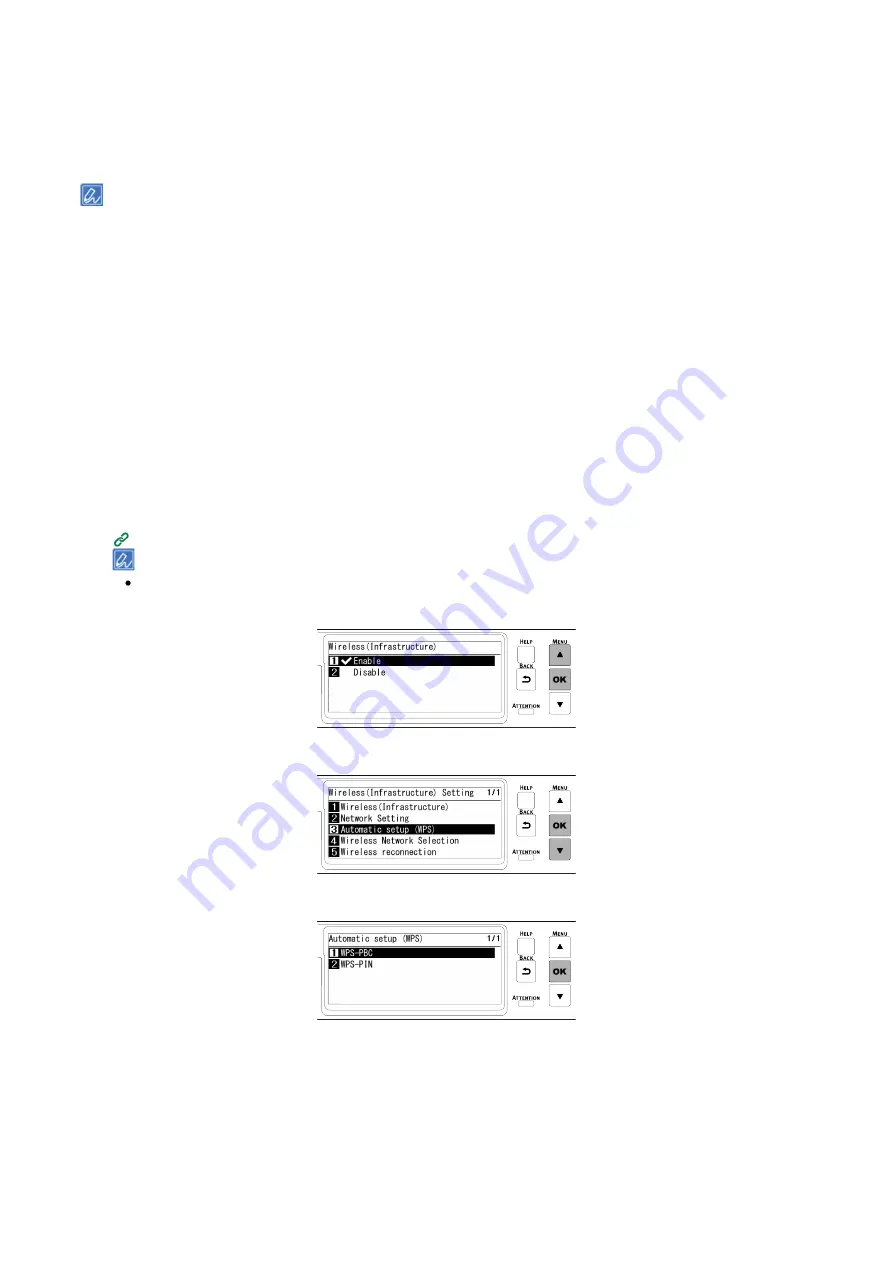
Press the scroll button ▲ on the operator panel several times to select [Wireless(Infrastructure) 

Setting], and press «OK». 

Input the admin password using the numeric keypad, and press «OK». 


Admin password

(P.114) 


  "It is not possible to use the wireless(AP Mode) at the same time." will be displayed for about 5 seconds. 

Press ▲ to select [Enable], and press «OK».


Press ▼ several times to select [Automatic setup (WPS)], and press «OK».


Check that [WPS-PBC] is selected, and press «OK». 


Содержание C650/ES6450

Страница 1: ...C650 ES6450 Basic Operation Guide...

Страница 2: ...g paper 70 Applicable paper 70 Inapplicable paper 72 Paper precautions by type 72 Paper applicable to each tray 74 Loading paper in Tray 1 74 Loading paper in Tray 2 3 4 Optional 76 Loading paper in t...

Страница 3: ...t 132 Replacing the belt unit 133 Replacing the fuser unit 135 Cleaning the main unit and the parts 137 Cleaning the LED head 137 Cleaning the surface of the main unit 138 Cleaning paper feed rollers...

Страница 4: ...Getting started 4 Getting started Safety precautions 5 General cautions 6 Preface 8 Trademarks 9 About this manual 10 Features of this machine 12...

Страница 5: ...Safety precautions Read this manual for your safety before using the product Mishandling due to ignoring this display may cause death or serious injury Mishandling due to ignoring this display may cau...

Страница 6: ...ally disconnect the power plug from the outlet and clean the base of the prongs and between the prongs Leaving the power plug inside the outlet for a long period of time may cause a fire due to short...

Страница 7: ...romptly with a large quantity of water Consult a physician as necessary Do not disassemble or forcibly open the image drum toner cartridge or waste toner box Doing so may scatter the toner which may b...

Страница 8: ...mpt to induce vomiting If inhaled move the person to an open area for fresh air Seek medical attention If it gets into the eyes flush with large amounts of water for at least 15 minutes keeping eyelid...

Страница 9: ...nufacturer has determined that this product meets the ENERGY STAR guidelines for energy efficiency Target countries of the ENERGY STAR program are the United States Canada and Japan It is not applicab...

Страница 10: ...related to the instructions contained in this manual Copyrights All rights belong to Oki Electric Industry Co Ltd This manual may not be reproduced transcribed or translated without permission Be sur...

Страница 11: ...board Indicates menu names item names options etc displayed on the display Indicates menus windows and dialog box names displayed on the PC screen They can be clearly distinguished in the description...

Страница 12: ...mparison with conventional models Massive printing possible with the extension tray Up to three extension trays can be installed Easy troubleshooting by watching the display The troubleshooting hint i...

Страница 13: ...chine Installation 14 Unpacking 16 Checking accessories 18 Installing the starter toner cartridge 19 Installing options 20 Connecting the power cord 31 Loading paper in the tray 32 Connecting via a wi...

Страница 14: ...ons such as alcohol and thinners Do not install this machine within the reach of children or infants Do not install this machine in an unstable location e g unsteady table or sloping surface Do not in...

Страница 15: ...ide this machine may rise and the printing speed may slow down Side view When the rear output tray is closed and a cable with angled connector is used Depending on the installation environment the tem...

Страница 16: ...n parts can easily get damaged handle with adequate care Do not expose the image drum to direct sunlight or strong light exceeding approx 1 500 lux Do not leave it for more than 5 minutes even under r...

Страница 17: ...the PC after preparing this machine 17 3 Lift this machine and place it at the installation site 4 Remove the drying agent on the top of this machine To use the optional expansion tray see Installing...

Страница 18: ...with this machine first If you install consumables other than the accessories first the service life may not be displayed correctly or the accessories may not be usable later Main unit By default an...

Страница 19: ...nstall a starter toner cartridge that has been used in another machine The remaining toner may not be displayed correctly 1 Pull the front cover open lever blue to open the front cover 2 Take the blac...

Страница 20: ...n tray unit Description Install it to increase the quantity of paper that can be loaded in this machine Up to 3 levels can be expanded Dedicated caster stand Description With it installed the machine...

Страница 21: ...dule may be damaged Turning the power off P 69 2 Open the wireless LAN module cover on the side of this machine 3 Pull out the connector and insert it into the wireless LAN module 4 Insert the wireles...

Страница 22: ...ss and press OK 14 When Are You Sure is displayed check that Yes is selected and press OK 15 Wait until the standby screen appears as this machine restarts 16 Enable Wireless Infrastructure or Wireles...

Страница 23: ...sition shifts correct the printing position for each extension tray For details see Correcting the print position of the tray User s Manual Model N36810A Doing so may cause injury This machine weighs...

Страница 24: ...rays aligned on the right side and front gently stack them so that the protrusions of the expansion tray fit into the holes on the bottom of the main unit 6 Fix the main unit and the expansion trays b...

Страница 25: ...he operator panel several times to select Configuration and press OK 10 Check that Tray Count is selected and press OK 11 Make sure the display shows the installed expansion tray 12 After confirming t...

Страница 26: ...ti tip feet and the attached fixing parts to avoid the risk of tipping The packing box and buffer materials are required to ship the dedicated caster stand Do not discard them but store them safely Mo...

Страница 27: ...ide down 5 Turn the dedicated caster stand back and mount the positioning pin x 2 Rotate to fix the positioning pin x 2 with a flat head screwdriver 6 Turn off this machine and remove the power cord a...

Страница 28: ...main unit or the extension tray and the dedicated caster stand with the metal fixtures x 2 and the screws x 4 by using a Phillips head screwdriver The figure shows an example of fixing the expansion t...

Страница 29: ...expansion trays are installed with the main unit and the expansion trays aligned on the right side and front gently stack them so that the protrusions of the expansion tray fit into the holes on the...

Страница 30: ...d the risk of tipping Do not press on the back of this machine or the image drum basket when the output tray is open and the image drum is pulled out Do not press on the cassette from above when the c...

Страница 31: ...plugging or unplugging the power cord Insert the power cord fully into the outlet Do not plug or unplug the power cord with wet hands Do not route the power cord wherever it could be stepped on Also d...

Страница 32: ...r paper is loaded see Loading paper P 70 1 Pull out the paper cassette 2 Slide the paper guide and the blue part of the paper stopper to fit the size of the paper to be loaded 3 Shuffle the paper well...

Страница 33: ...Connecting to the PC after preparing this machine 33 5 Return the paper cassette to this machine 6 Set the size type and weight of the paper on the operator panel Loading paper P 70...

Страница 34: ...lug one end of the LAN cable into the network interface connector LAN1 of this machine 4 Plug the other end of LAN cable into the hub Then set the network information like the IP address on this machi...

Страница 35: ...password P 114 4 Check that Network Setup is selected and press OK 5 Press to select Wired LAN1 Setup and press OK 6 Press to select IP Address Set and press OK When you set the IP address manually pr...

Страница 36: ...sor has returned to the first 3 digit and press BACK 10 Press to select Subnet Mask and press OK 11 Input the subnet mask in the same way as the IP address Press OK after inputting all the information...

Страница 37: ...several times to select Configuration and press OK 2 Press 5 on the Configuration screen 3 Check that Network Setup is selected and press OK 4 Press to select Wired LAN1 Information and press OK 5 Pre...

Страница 38: ...e of this machine is not displayed the network connection between the PC or other terminals and this machine has failed Check if IP Address Set IPv4 Address Subnet Mask and Gateway Address of this mac...

Страница 39: ...d at the same time Since the communication may be unstable if wired LAN1 and wireless LAN are connected to the same subnet please connect to a different subnet Type Infrastructure AP mode Connectio n...

Страница 40: ...dio Law Use it indoors only Use it indoor only When using 2 4GHz for a connection use it within the range of 1 to 11ch 12ch and 13ch are applicable only to devices for Korea Please follow the laws and...

Страница 41: ...Mode at the same time will be displayed for about 5 seconds 3 Press to select Enable and press OK After setting wireless AP Mode to Disable if a screen appears to ask you to check whether to enable w...

Страница 42: ...Infrastructure Setting and press OK 2 Input the admin password using the numeric keypad and press OK Admin password P 114 It is not possible to use the wireless AP Mode at the same time will be displa...

Страница 43: ...s to select Subnet Mask and press OK 10 Input the subnet mask in the same way as the IP address Press OK after inputting all the digits 11 Press to select Gateway Address and press OK 12 Input the gat...

Страница 44: ...of push button for easy setup WPS button and the time for which the button is pressed in the User s Manual enclosed with the wireless LAN access point 2 Check that the wireless LAN access point is act...

Страница 45: ...t or Connection failed is displayed repeat the procedure from Step 1 or try Connecting by selecting a wireless LAN access point from the operator panel Connecting by selecting a wireless LAN access po...

Страница 46: ...only Manual Setup is displayed In that case make settings by following Connecting by setting manually from the operator panel 8 When the encryption key entry screen suitable for the encryption method...

Страница 47: ...int information SSID encryption method encrypted key manually and connect to the wireless LAN 1 Check and take a note of the SSID and encryption key on the wireless LAN access point or in the enclosed...

Страница 48: ...t of SSID of connectible wireless LAN access points is displayed Press several times to select Manual Setup at the end of the list and press OK 7 Check that SSID is selected and press OK 8 Input the S...

Страница 49: ...cess point is completed Go to 6 Checking the connection from a PC When Not connected to wireless access point is displayed repeat the procedure from Step 4 If you cannot connect see Troubleshooting fo...

Страница 50: ...tup is selected and press OK 5 Check that General Setup is selected and press OK 6 Press to select Enabling Default Gateway and press OK 7 Press to select Wireless Infrastructure and press OK 8 Press...

Страница 51: ...ork connection between the PC or other terminals and this machine has failed Check that IP Address Set IPv4 Address Subnet Mask Gateway Address and Enabling Default Gateway have been set correctly for...

Страница 52: ...that Basic Settings is selected and press OK 6 Check that Extended Network is selected and press OK 7 Press to select Wireless and press OK 8 When Are You Sure is displayed check that Yes is selected...

Страница 53: ...3 Connecting with a device There are two ways as follows Connecting automatically Push button Connecting manually Connecting automatically Push button If the wireless terminal supports WPS PBC push b...

Страница 54: ...hod is displayed for about 2 minutes Start the push button on the wireless terminal while it is displayed While Running pushbutton method is displayed the operator panel of this machine is disabled 8...

Страница 55: ...rd of this machine are displayed The screens shown here are examples and they may differ from the actual display 6 Input SSID and Password of this machine confirmed in Step 5 in the wireless terminal...

Страница 56: ...B To connect in the USB 2 0 hi speed mode use a USB cable compliant with USB 2 0 hi speed specifications 2 Power off this machine 3 Plug one end of the USB cable into the USB interface connector of th...

Страница 57: ...0 12 OS X 10 11 The screen display may differ from the description depending on the version of Windows and macOS or the specific printer driver Types of printer driver There are two types of printer d...

Страница 58: ...n the Welcome screen 5 Read the software license agreement and click Accept 6 Read the environmental advice and click Go 7 Click either Network Connection or USB Connection depending on the connection...

Страница 59: ...on will begin The following software will be installed PCL6 printer driver including Network Extension Color Swatch Utility FAQs Monitoring Tool Other software is installed from either Batch Install o...

Страница 60: ...ars click Yes After the update is completed click Go 13 Click Go If the following screen appears click Yes 14 Click Exit Now installation is completed If you install options like the expansion tray un...

Страница 61: ...lick Printers and Scanners 8 Click and select Add Printer or Scanner when the menu appears If you cannot click click the key mark 9 Click Default 10 Select this machine and select OKI C650 PS from Dri...

Страница 62: ...been installed change the printer driver settings with the following procedure after installing the printer driver Installing software on a PC P 57 To follow this procedure it is necessary to log int...

Страница 63: ...trays are trays 1 2 3 4 so input 4 5 Click OK For Windows PS printer driver 1 Open the Devices and Printers How to open the printer folder P 112 2 Right click on the icon of OKI C650 PS and select Pri...

Страница 64: ...his machine 64 For macOS 1 Select System Preferences from the Apple menu 2 Click Print Scan 3 Select this machine and click Options and Supplies 4 Select the Options tab 5 Select the total number of t...

Страница 65: ...Basic operations 65 Basic operations Parts identification 66 Turning the power on off 69 Loading paper 70 Setting the output bin 82 Checking the configuration 84 How to use levers L1 and L2 86...

Страница 66: ...ning the front cover 4 Fuser unit This unit fixes the toner to the paper 5 Power switch Turns on off the power of the main unit Lights blue when the power is turned on and lights off when the power is...

Страница 67: ...ver L2 The lever used to lift up the cover of the output tray 20 Lever L1 The lever uses to replace the image drum 21 Belt unit The unit to convey the paper 22 Handle L3 The handle used to pull out th...

Страница 68: ...31 Interface unit There is a connector to connect to a PC 32 USB interface connector This is where the USB cable is plugged in when the computer and the main unit is connected with a USB cable 33 Acc...

Страница 69: ...y and the LED lamp of the power switch will flash at intervals of approx 1 second Wait a moment and this machine will be powered off automatically and the LED lamp of the power switch will turn off If...

Страница 70: ...e paper that fulfills the quality weight and surface finish conditions Please use electrophotographic paper If you are printing on non recommended paper thoroughly test the print quality and paper tra...

Страница 71: ...Equivalent to plain paper 64 256 g m2 Media whose pigment or ink used to color the paper is heat resistant and can withstand 230 C Media made of electrophotographic paper with the same features as pl...

Страница 72: ...rbon paper non carbon paper thermal paper and pressure sensitive paper Thermal transfer printer paper ink jet paper wet PPC paper copying paper Japanese paper etc Envelopes sticked with stamps Envelop...

Страница 73: ...er properly so that the face side is the printing side The paper is wrapped in moisture proof paper to prevent moisture Please use the paper as early as possible after opening its package If the paper...

Страница 74: ...Media type Media size Media weight Applicable number of sheets Plain Partially printed paper Colored paper A4 A5 A6 B5 B6 Letter Legal 13 inches Legal 13 5 inches Legal 14 inches Executive Statement...

Страница 75: ...he OK button and change the settings of paper size media type and media weight accordingly Be cautious for the orientation of paper that can be loaded in either portrait or landscape like A5 size 2 Sl...

Страница 76: ...fit the paper size Set it to OTHER when you have loaded the paper of a standard size not available on the paper size dial If you pull out the paper cassette with the power on Change tray setting may a...

Страница 77: ...from top Do not exceed the mark on the paper guide when loading paper 6 Check that the size and orientation of the loaded paper well match the settings of the paper size dial If the size and the orie...

Страница 78: ...ded and then load them together Do not insert anything other than print paper into the MP tray Do not leave paper in the MP tray for an extended period of time Dust and dirt will adhere to the paper a...

Страница 79: ...gly 8 Move the paper placement cover downward The paper cannot be fed without lowering the paper placement cover If you always print on paper of the same size and type from the MP tray register the lo...

Страница 80: ...nd then BACK 6 Press ON LINE to return to the standby screen For Tray 2 3 4 1 Check that Ready To Print appears on the display 2 To set the paper size of Tray 2 press the keys in the following order F...

Страница 81: ...edium Heavy 105 120 g m2 Heavy 121 176 g m2 Ultra Heavy 1 177 220 g m2 Ultra Heavy 2 221 256 g m2 Ultra Heavy 3 Storing paper Please keep the paper under the following conditions to maintain the quali...

Страница 82: ...ot open or close the output tray during printing Doing so may cause a paper jam Output tray The paper is output with the printing side down in the order in which they are printed Check that the rear o...

Страница 83: ...to print on envelopes labels or custom sized paper The paper is output with the printing side up in the reverse order to which they are printed 1 Open the rear output tray at the back of this machine...

Страница 84: ...Usage Report 1 Check that Ready To Print appears on the display If the machine is in the power save mode press POWER SAVE to restore 2 Press Fn on the operator panel 3 On the function number screen p...

Страница 85: ...r panel 1 Check that Ready To Print appears on the display If the machine is in the power save mode press POWER SAVE to restore 2 Press the scroll button on the operator panel several times to select...

Страница 86: ...the image drum and to clean the LED head Replacing the image drum P 128 Cleaning the LED head P 137 After opening the front cover operate the L1 lever first and then the L2 lever After the operation...

Страница 87: ...133 When paper is jammed P 148 After opening the front cover pull the L2 lever After the operation both the output tray and the image drum basket are integrated and raised No Name 1 Output tray 2 Ima...

Страница 88: ...anel 88 Changing settings from the operator panel Parts identification of the operator panel 89 Adjusting the display orientation 90 Inputting text 91 Changing settings 92 Adjusting the buzzer volume...

Страница 89: ...CK or CANCEL button 8 POWER SAVE button Turns on or off the power save mode Cancels the sleep mode Lights green in the power save mode and flashes green in the sleep mode 9 Numeric keypad Inputs alpha...

Страница 90: ...djusting the display orientation You can adjust the angle so that it is easier to watch the display 1 Put your finger in the recess on the left side of the display and raise the display towards you To...

Страница 91: ...1 1 1 2 2 a b c A B C 2 3 3 d e f D E F 3 4 4 g h i G H I 4 5 5 j k l J K L 5 6 6 m n o M N O 6 7 7 p q r s P Q R S 7 8 8 t u v T U V 8 9 9 w x y z W X Y Z 9 0 0 space 0 Fn _ space If the setting val...

Страница 92: ...e item to be set and press OK Repeat until you see the category of the item to be set The display color of the selected item is highlighted 3 Press or several times to select the item to be set and th...

Страница 93: ...ric keypad and press OK 4 When the menu is displayed check or change the settings Function Number List Function No Corresponding menu item 1 Shared Print Stored Job 2 Private Print Encrypted Job 10 Me...

Страница 94: ...uto Power Off Time 210 Error Report 220 Print Position Adjust MP tray 221 Print Position Adjust Tray 1 222 Print Position Adjust Tray 2 223 Print Position Adjust Tray 3 224 Print Position Adjust Tray...

Страница 95: ...d buzzer 1 Press the scroll button on the operator panel several times to select Admin Setup and press OK 2 Input the admin password using the numeric keypad and press OK Admin password P 114 3 Press...

Страница 96: ...own depending on the printing environment or the usage conditions 1 Check that Ready To Print appears on the display If the machine is in the power save mode press POWER SAVE to restore 2 Press Fn on...

Страница 97: ...select the time to set and press OK 5 Press ON LINE to return to the standby screen Restrictions of the power save function The sleep mode will not be entered in the following cases When an error has...

Страница 98: ...lowing cases With the factory default settings Auto Power Off does not work when a network wired wireless is connected When an error has occurred Follow the procedure below to change the Auto Power Of...

Страница 99: ...r 2 hours 3 hours 4 hours 8 hours 12 hours 18 hours and 24 hours 1 Check that Ready To Print appears on the display If the machine is in the power save mode press POWER SAVE to restore 2 Press Fn on t...

Страница 100: ...Printing 100 Printing Printing from a PC 101 Screens and functions of the printer driver 103...

Страница 101: ...lect OKI C650 PCL6 from Select Printer 4 Click Preferences or Properties 5 Select the loaded paper size from Size in the Setup tab 6 Select the tray to be printed from in Paper Source If you cannot se...

Страница 102: ...Click Advanced 8 Click Paper Size and select the loaded paper size from the drop down list 9 Set other necessary items 10 Click OK 11 Printing starts For macOS 1 Open the file to be printed 2 Select...

Страница 103: ...a type 6 Weight Sets the media weight 7 Finishing Mode Sets multicast printing booklet printing poster printing etc 8 2 Sided Printing Sets the duplex printing 9 Orientation Sets the printing orientat...

Страница 104: ...sent to the printer is in PCL format or as an image 6 Advanced Make other printing settings 7 Default Restores the settings of each item in the tab to the initial values Extend tab No Item Description...

Страница 105: ...ecifies the number of pages to be printed on one sheet of paper and booklet printing 5 Layout image Displays a sample image of the print layout 6 Advanced You can make detail settings such as the prin...

Страница 106: ...watermark 5 Overlays Set for printing with an overlapping format registered in the printer beforehand 6 Advanced Other settings can be made 7 User authentication Sets the user authentication 8 About D...

Страница 107: ...sheet of paper 3 Border Specifies the type of borders 4 Two Sided Specifies settings for printing on both sides 5 Reverse page orientation Checked to print with the page direction reversed 6 Flip hori...

Страница 108: ...t by zooming in out according to the media size 5 Destination Paper Size Specifies the size of the paper to be printed when Scale to ft paper size is checked 6 Scale down only Specifies settings for p...

Страница 109: ...ription 1 Print Cover Page Specifies the cover printing 2 Cover Page Type Specifies the text string for cover printing Color panel No Item Description 1 Grayscale Print in monochrome 2 Color Specifies...

Страница 110: ...er authentication Checked to set user authentication for printing 2 User name The user name for user authentication 3 Password The password for user authentication 4 Authentication type Specifies the...

Страница 111: ...ob Type Options is available 2 Job Type Options Specifies the password for printing the job name displayed on the panel Supply Level panel No Item Description 1 Consumables Displays the usage status o...

Страница 112: ...Click Start to display the application list 2 Select Windows System Tool Control Panel Devices and Printers For Windows Server 2012 R2 Windows Server 2016 1 Select Control Panel View devices and print...

Страница 113: ...Management of this machine 113 Management of this machine Admin password 114...

Страница 114: ...ial number AB01234567 Admin password ab01234567 The serial number may be displayed as Serial Number or Serial No Check the machine s serial number with one of the following methods Check by the displa...

Страница 115: ...nverted string as the admin password Checking by printing the menu map On the menu map the serial number is displayed as Serial No 1 Print the menu map Printing the menu map configuration P 84 2 Check...

Страница 116: ...swords P 114 1 Check that Ready To Print appears on the display If the machine is in the power save mode press POWER SAVE to restore 2 Press the scroll button on the operator panel several times to se...

Страница 117: ...rd the charged service by maintenance staff will be necessary If the machine is in the power save mode press POWER SAVE to restore This section describes how to change the factory default admin passwo...

Страница 118: ...ine 118 6 Press OK again to display the Verify Password screen 7 Input the password again and press OK 8 When OK is pressed again the password has been changed and the screen returns to Admin Setup Ad...

Страница 119: ...er cartridge and the waste toner box 123 Replacing the toner cartridge C M Y 126 Replacing the image drum 128 Service life and replacement cycle of maintenance parts 131 Replacing the belt unit 133 Re...

Страница 120: ...haled gargle with a lot of water and move the person to a place with fresh air Consult a physician as necessary When toner gets contact with the skin of your hands etc wash it off with soapy water It...

Страница 121: ...Failures caused by using non genuine consumables may void the warranty or maintenance contract The use of non genuine consumables will not necessarily cause failures but please fully take notice of su...

Страница 122: ...e with adequate care Do not expose the image drum to direct sunlight or strong light About 1 500 lux or above Do not leave it uncovered for more than 5 minutes even under room lighting Use genuine OKI...

Страница 123: ...er box first and then the black K toner cartridge 1 Press the knob on the lower left corner on the front of the machine and open the waste toner box cover toward you 2 Put your finger on the recess of...

Страница 124: ...toner cartridge both horizontally and vertically for several times 8 Pull the front cover open lever blue to open the front cover 9 Pull out the black K toner cartridge from the machine 10 Install the...

Страница 125: ...Maintenance 125 12 Press OK 13 Check that no error message appears on the display Please recycle the used toner cartridge and waste toner box...

Страница 126: ...o Replacing the black K toner cartridge and the waste toner box P 123 1 Remove the new toner cartridge of the color to be replaced from its packing case 2 Shake the new toner cartridge both horizontal...

Страница 127: ...Maintenance 127 6 Close the front cover firmly with your both hands Please recycle the used toner cartridge...

Страница 128: ...de the machine If the two red triangle marks are not aligned correctly you cannot proceed to the procedure of replacing the image drum 3 Pull the L2 lever and lift the output tray to the stop position...

Страница 129: ...under room lighting The image drum is not fixed in the main unit You can just lift to remove it 7 Take the new image drum of the color to be replaced out of its box 8 Take out the desiccant of the new...

Страница 130: ...the way in The output tray cannot be closed unless the image drum basket is pushed all the way in 11 Close the output tray and push both sides down from top 12 Press the L1 lever all the way in The f...

Страница 131: ...s arrived A message indicating replacement of the belt unit may be displayed without displaying a message indicating that the time for replacement is approaching In this case please replace the belt u...

Страница 132: ...State of this machine Printing is possible but the fuser unit is approaching the end of its service life Printing stops About 1 500 pages can be printed from when the time for replacement is approachi...

Страница 133: ...tion 3 Remove the belt unit by holding its blue handle Doing so may cause burns Do not touch the fuser unit because it is hot Because image drums green parts can easily get damaged handle with adequat...

Страница 134: ...4 5 Install the belt unit in this machine by holding its blue handle 6 Close the output tray and push both sides down firmly from top 7 Close the front cover firmly with both hands Please recycle the...

Страница 135: ...ally 2 Remove the fuser unit from this machine by holding its left and right handles Doing so may cause burns When the fuser unit is hot wait until it cools down before any operation Do not expose thi...

Страница 136: ...and install the fuser unit into this machine 5 Push down the left and right handles of the fuser unit to lock Make sure that the fuser unit does not float from the top of the output tray If floating t...

Страница 137: ...light About 1 500 lux or above Do not leave it uncovered for more than 5 minutes even under room lighting 1 Power off this machine 2 Pull the front cover open lever blue to open the front cover 3 Pull...

Страница 138: ...n 5 minutes even under room lighting 6 Close the output tray and push both sides down from top 7 Press the L1 lever all the way in 8 Close the front cover firmly with both hands Cleaning the surface o...

Страница 139: ...n the separation roller of the paper cassette and the paper feed roller inside this machine If paper jams persist even after the paper feed roller is cleaned it is recommended to replace the paper fee...

Страница 140: ...cassette to this machine Cleaning the paper feed roller MP tray If paper jams occur frequently clean the paper feed roller If paper jams persist even after the paper feed roller is cleaned it is reco...

Страница 141: ...the protrusion of the left arm of the MP tray from the groove and lift it up 6 Lift up the paper placement cover until it attaches to the machine 7 Press down on the center of the MP tray and then pre...

Страница 142: ...a cloth slightly moistened with water while rotating it in the arrow direction 10 Press down on the center of the MP tray until the left trapezoidal part of the separation roller cover fits into the...

Страница 143: ...nto the innermost position If it is hard to insert slide to install the paper feed roller without gear while rotating it downward 13 Wipe the paper feed roller without gear with gear with a cloth slig...

Страница 144: ...t hooking the protrusion of the arm to the correct position the paper placement cover may be broken Be sure to hook it in the correct position 17 Slide the manual feeder guide outward 18 Close the MP...

Страница 145: ...t clean the resist roller to improve the printing 1 Pull the front cover open lever blue to open the front cover 2 Wipe the metal parts a and b of the resist roller visible on the front with soft tiss...

Страница 146: ...Troubleshooting 146 Troubleshooting When an error message appears on the display 147 When paper is jammed 148...

Страница 147: ...ange the indication on the display If a search keyword is displayed you can search for a solution by inputting it in Search Keyword of Frequently Asked Questions FAQs on the website or your smartphone...

Страница 148: ...e output tray until it reaches the stop position 4 Remove the paper left on the belt unit if any Doing so may cause burns Do not touch the fuser unit because it is hot Because image drums green parts...

Страница 149: ...belt unit if any 7 Reset the belt unit 8 Close the output tray and push both sides down from top 9 Lift the left and right handles of the fuser unit at the back of the output tray until a click is hea...

Страница 150: ...to direct sunlight or strong light About 1 500 lux or above Do not leave it uncovered for more than 5 minutes even under room lighting 11 Remove any paper left in the machine 12 If paper is jammed in...

Страница 151: ...tilt its left and right handles inward and lock the fuser unit Make sure that the fuser unit does not float from the top of the output tray If floating the fuser unit will not be recognized so that it...

Страница 152: ...on the belt unit if any Doing so may cause burns Do not touch the fuser unit because it is hot Because image drums green parts can easily get damaged handle with adequate care Do not expose the image...

Страница 153: ...under the belt unit if any 7 Reset the belt unit 8 Close the output tray and push both sides down from top 9 Close the front cover firmly with both hands For the error code 380 1 Pull the front cover...

Страница 154: ...Close the front cover firmly with both hands For the error code 381 1 Remove the jammed paper from the output exit 2 Pull the front cover open lever blue to open the front cover 3 Pull the L2 lever an...

Страница 155: ...damaged handle with adequate care Do not expose the image drum to direct sunlight or strong light About 1 500 lux or above Do not leave it uncovered for more than 5 minutes even under room lighting 5...

Страница 156: ...e belt unit if any Doing so may cause burns Do not touch the fuser unit because it is hot Because image drums green parts can easily get damaged handle with adequate care Do not expose the image drum...

Страница 157: ...Holding both the left and right handles of the fuser unit remove the fuser unit from this machine Doing so may cause burns When the fuser unit is hot wait until it cools down before any operation Do...

Страница 158: ...o not pull out in the reverse direction 10 With the warning label of the fuser unit facing you hold both the left and right handles 11 Place the fuser unit in this machine tilt its left and right hand...

Страница 159: ...ly pull out the paper from its rear edge 5 Close the front cover firmly with your both hands 6 If you are using a MP tray open the MP tray and load paper with the print side up For how to load paper i...

Страница 160: ...the paper cassette 2 Remove the jammed paper If no paper is jammed feeding has failed Reduce the number of paper loaded in the paper cassette Also make sure that the paper stopper position matches the...

Страница 161: ...paper Then remove the remaining paper inside the machine This section explains how to remove the paper from Tray 2 as an example 1 Pull out the paper cassette 2 Remove the remaining paper 3 Return the...

Страница 162: ...es the stop position 8 Remove the paper left on the belt unit if any Doing so may cause burns Do not touch the fuser unit because it is hot Because image drums green parts can easily get damaged handl...

Страница 163: ...elt unit if any 11 Reset the belt unit 12 Close the output tray and push both sides down from top 13 Lift the left and right handles of the fuser unit at the back of the output tray until a noise is h...

Страница 164: ...t 1 500 lux or above Do not leave it uncovered for more than 5 minutes even under room lighting 15 Remove the paper left in the machine if any 16 If paper is jammed in the fuser unit with the warning...

Страница 165: ...ft and right handles inward and lock the fuser unit Make sure that the fuser unit does not float from the top of the output tray If floating the fuser unit will not be recognized so that it is not pos...

Страница 166: ...Appendix 166 Appendix Specifications 167 Dimensions 171 Menu tree 173...

Страница 167: ...lay screen 2 9 inch monochrome graphic panel 320 x 128 dots Compatible OS Windows 10 Windows 8 1 Windows 8 Windows 7 Windows Server 2019 Windows Server 2016 Windows Server 2012 R2 Windows Server 2012...

Страница 168: ...paper feeding from Tray 1 the MP tray and the expansion tray unit Optional Manual feeding from the MP tray Feeding capacity Tray 1 250 sheets 80 g m2 with the total weight of 25 mm or less MP tray 100...

Страница 169: ...compliance could void the user s authority to operate the equipment Note This equipment has been tested and found to comply with the limits for a Class B digital device pursuant to part 15 of the FCC...

Страница 170: ...tion exposure limits set forth for an uncontrolled environment and meets the FCC radio frequency RF Exposure Guidelines and RSS 102 of the IC radio frequency RF Exposure rules This equipment should be...

Страница 171: ...Appendix 171 Dimensions Plan view Side view...

Страница 172: ...Appendix 172 With options installed...

Страница 173: ...dress Wireless Infrastructure Information Firmware Version Wireless Infrastructure MAC Address IPv6 Address Local IPv6 Address Stateless Address IPv4 Address Subnet Mask Gateway Address Short Printer...

Страница 174: ...Fn34 Other Size Media Weight Fn24 Other Size Tray3 Config Paper Size Fn30 Y Dimension Fn42 X Dimension Fn31 Y Dimension Fn32 X Dimension Fn41 Tray2 Config Paper Size Fn20 Media Type Fn23 Tray Usage F...

Страница 175: ...Subnet Mask Hex Dump Fn237 Easy Setup Sleep Time Fn201 Auto Power Off Time Fn202 Silent Mode Clearable Warning Auto Continue Manual Timeout Power Save Time Fn200 Error Report Fn210 Timeout InJob Timeo...

Страница 176: ...tion Wireless Infrastructure Setting IP Address Set IPv4 Address Subnet Mask Gateway Address DHCPv6 Automatic setup WPS WPS PBC You must input an administrator password Connected Host Serial Number Of...

Страница 177: ...n Line Pitch Font Condense IBM PPR Setup Print Margin Symbol Set SIDM Setup SIDM Manual ID SIDM Manual2 ID Tray1 Tray2 Private Print Setup Verify job option Erase job option Keep job for Character Set...

Страница 178: ...easurement Others Setup Paper Feed Roller Counter Clear MP Tray Clear Tray1 Clear Time Setting Power Setup Auto Power Off Time Zone Daylight Saving Setting method Tray Setup AirPrint Buzzer Volume Idl...

Страница 179: ...Wireless reconnection Wireless AP Mode Setting You must input an administrator password Automatic Setup PushButton Manual Setup Wireless AP Mode Manual Setup SSID Security WEP Key AP Mode User Setting...

Страница 180: ...EE8001 1659Z002 Rev2...

Отзывы: