


2 - 3
Chapter 2 Diagnostics
3. Main Menu
3.1 Navigating through the Diagnostic Menus
Four buttons are used to navigate through the diagnostic menus and sub-menus, (
W
,
X
,
S
,
T
). From
the initial menu selection “Output Tests” (see 3.2), pressing the “
T
” button moves down the menu to
“Input Tests” then to “Alignment” and so on. Pressing “
S
” moves up through the menu. The menus are
in the form of a continuous loop. When you reach the last selection on the menu, pressing “
T
” will take
you to the top of the menu.
With the desired menu displayed, pressing “
X
” activates that menu. Any sub-menu items may be
accessed by using the “
T
“and “
S
“ buttons. If the selected menu has no sub-menus, pressing “
X
" will
start the test. If the test is a motor, the motor will run. If the test is a solenoid, the solenoid will energize.
If the selected menu has a sub-menu, use the “
T
” or “
S
” buttons to move down or up through the
menu selections. When the desired menu is displayed, press “
X
” to activate the menu. In some cases
the sub-menu may be a value. The value may be Yes / No or a number. Use the “
T
“and “
S
“ buttons to
change the value and the “
X
” button to lock in the new value.
Use the “
W
” button to back out of sub-menus to the next higher level. Repeatedly pressing the “
W
” but-
ton will return you to the Ready condition.
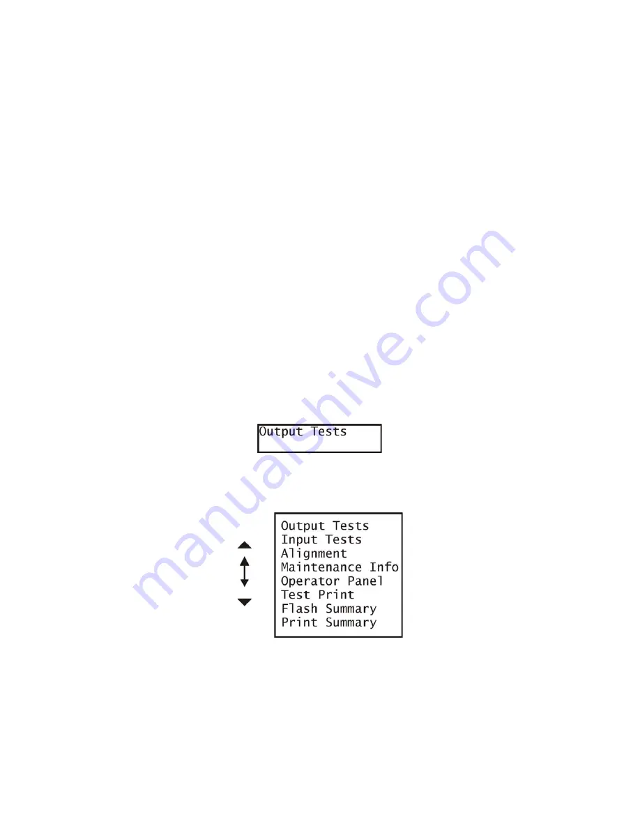
3.2 Main Menu
When you first enter diagnostics, the LCD will display “Output Tests” and the first selection of the main
menu.
The complete Main Menu is shown below. Pressing the “
T
” or “
S
” will scroll through the menu list.
Содержание B6500 Series
Страница 1: ...Laser Printer OKI B6500 Service Manual 060810A...
Страница 16: ...xv Blank Page...
Страница 20: ...Chapter 1 Troubleshooting Chapter 1 Troubleshooting CONTENTS Blank Page...
Страница 88: ...1 68 Chapter 1 Troubleshooting Blank Page...
Страница 160: ...1 140 Chapter 1 Troubleshooting Blank Page...
Страница 162: ...1 142 Chapter 1 Troubleshooting Blank Page...
Страница 164: ...Chapter 2 Printer Diagnostics Chapter 2 Diagnostics CONTENTS 11 Print Summary 2 16...
Страница 194: ...3 10 Chapter 3 Removal and Replacement Procedures RRPs RRP2 150 PAPER CASSETTE...
Страница 213: ...3 29 Chapter 3 Removal and Replacement Procedures RRPs RRP3 550 PAPER CASSETTE...
Страница 240: ...3 56 Chapter 3 Removal and Replacement Procedures RRPs RRP4 150 paper Feeder...
Страница 257: ...3 73 Chapter 3 Removal and Replacement Procedures RRPs RRP5 550 Paper Feeder...
Страница 277: ...3 93 Chapter 3 Removal and Replacement Procedures RRPs RRP6 Xerographics...
Страница 302: ...3 118 Chapter 3 Removal and Replacement Procedures RRPs RRP7 500 Paper Exit...
Страница 322: ...3 138 Chapter 3 Removal and Replacement Procedures RRPs RRP8 Frame Drive...
Страница 331: ...3 147 Chapter 3 Removal and Replacement Procedures RRPs RRP9 Electrical...
Страница 394: ...3 210 Chapter 3 Removal and Replacement Procedures RRPs...
Страница 403: ...3 219 Chapter 3 Removal and Replacement Procedures RRPs 4 Install the 550 FEEDER OPTION PL 12 2 RRP12 1...
Страница 454: ...3 270 Chapter 3 Removal and Replacement Procedures RRPs Blank Page...
Страница 456: ...Chapter 4 Plug Jack P J Connector Locations Chapter 4 Plug Jack P J Connector Locations CONTENTS Blank Page...
Страница 459: ...4 3 Chapter 4 Plug Jack P J Connector Locations Blank Page...
Страница 465: ...4 9 Chapter 4 Plug Jack P J Connector Locations 3 2 OCT Option P J Diagram...
Страница 468: ...4 12 Chapter 4 Plug Jack P J Connector Locations Blank Page...
Страница 470: ...Chapter 5 Parts Lists Chapter 5 Parts Lists CONTENTS Blank Page...
Страница 472: ...5 2 Chapter 5 Parts List PL 1 1 COVER ILLUSTRATION 2 Ref PL10 1 1 7 8 9 9 13 14 15 3 4 6 5 J25014AA 10 16 J244...
Страница 479: ...5 9 Chapter 5 Parts List Blank Page...
Страница 483: ...5 13 Chapter 5 Parts List Blank Page...
Страница 490: ...5 20 Chapter 5 Parts List PL 7 2 500 PAPER EXIT 2 2 OPTION FACE UP TRAY ILLUSTRA TION...
Страница 496: ...5 26 Chapter 5 Parts List OPTIONS PL 10 1 OPTION DUPLEX ILLUSTRATION...
Страница 501: ...5 31 Chapter 5 Parts List Blank Page...
Страница 529: ...6 19 Chapter 6 Principles of Operation J26119AA EP CARTRIDGE BTR ASSY...
Страница 531: ...6 21 Chapter 6 Principles of Operation LD Assembly JG6121AA SOS PWB Scanner Assembly...
Страница 535: ...6 25 Chapter 6 Principles of Operation...
Страница 547: ...6 37 Chapter 6 Principles of Operation J26615AA PWBA DUPLEX SWITCH DUPLEX SENSOR DUP MOTOR DUPLEX ROLL DUP FAN DUPLEX...
Страница 558: ...6 48 Chapter 6 Principles of Operation Blank Page...
Страница 560: ...Chapter 7 Wiring Diagrams and Signal Information Chapter 7 Wiring Diagrams and Signal Information CONTENTS Blank Page...
Страница 584: ...7 24 Chapter 7 Wiring Diagrams and Signal Information Blank Page...
Страница 608: ...Chapter 9 ESS Options Chapter 9 Controller ESS Options Contents Blank Page...
Страница 616: ...9 8 Chapter 9 ESS Options Blank Page...


