4-12
CHAPTER 4 MAINTENANCE PROCEDURES
4.3.1.1
Printed Circuit Board (4) and Power Board Replacement
In an effort to keep service costs down, it is suggested that if the Printed Circuit Board
(4) is suspected of being faulty, it should be replaced rather than repaired.
To replace the Printed Circuit Board (4) and Power Board, proceed as follows:
1. Disassemble the balance, refer to paragraph 4.3.1.
CAUTION
WHEN HANDLING THE PRINTED CIRCUIT
BOARD, HANDLE BY EDGES ONLY! DO
NOT TOUCH FOIL SIDE OF BOARD.
STATIC DISCHARGE MAY DAMAGE SOME
COMPONENTS.
2. The Printed Circuit Board (4) and Power Board are wired together by a
short flexible cable. These parts are available wired together as a kit, refer
to the parts list for part number if both boards are to be replaced. Remove the
flexible cable coming from the Transducer (8) from the connector on the
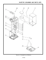
Printed Circuit Board (4) as shown in Figure 5-1.
3. Unclip the Printed Circuit Board (4) from the Base (1) and unclip the Power
Board from the Base (1). Remove both boards from the Base (1).
4. On 200 gram Balances, the EEPROM (U6) from the old PC Board must be
removed and installed in the new board.
5. Install the new Printed Circuit Board (4) and the Power Board to the Base (1).
Make sure that all of the clips are properly secured to the boards.
6. Connect the flexible cable from Transducer (8) to the connector on the Printed
Circuit Board (4).
7. Reassemble the Balance.
8. Check the performance of the balance and recalibrate.
4.3.1.2
LCD Display (12) Replacement
The LCD Display is fastened to the Cover (2) by an adhesive. The display is then
covered by the Function Label (13) which is also fastened to the Cover (2) by an
adhesive. If the LCD display must be replaced, the Function Label must also be
replaced since it will be destroyed upon removal.
Содержание SCOUT
Страница 1: ...OhausCorporation 29HanoverRoad FlorhamPark NJ 07932 0900 ELECTRONIC BALANCES SERVICE MANUAL TM...
Страница 6: ...i v...
Страница 10: ...1 4 CHAPTER 1 INTRODUCTION...
Страница 38: ...5 2 CHAPTER 5 DRAWINGS AND PARTS LISTS...
Страница 39: ...5 3 CHAPTER 5 DRAWINGS AND PARTS LISTS Figure 5 1 Exploded View of Balance 5 3 5 4...
Страница 43: ...SCOUT ELECTRONIC BALANCES P N 300040 010 R1198...
Страница 45: ...e e e...
Страница 47: ......


