4-11
CHAPTER 4 MAINTENANCE PROCEDURES
4.3.1 Disassembly (Cont.)
Mode
Off
Re Zero
On
COVER SCREW
TRANSDUCER
TM
Mode
Off
Re Zero
On
PLATFORM
RETAINING
SCREW
DOWN STOP
ADJUSTMENT
TM
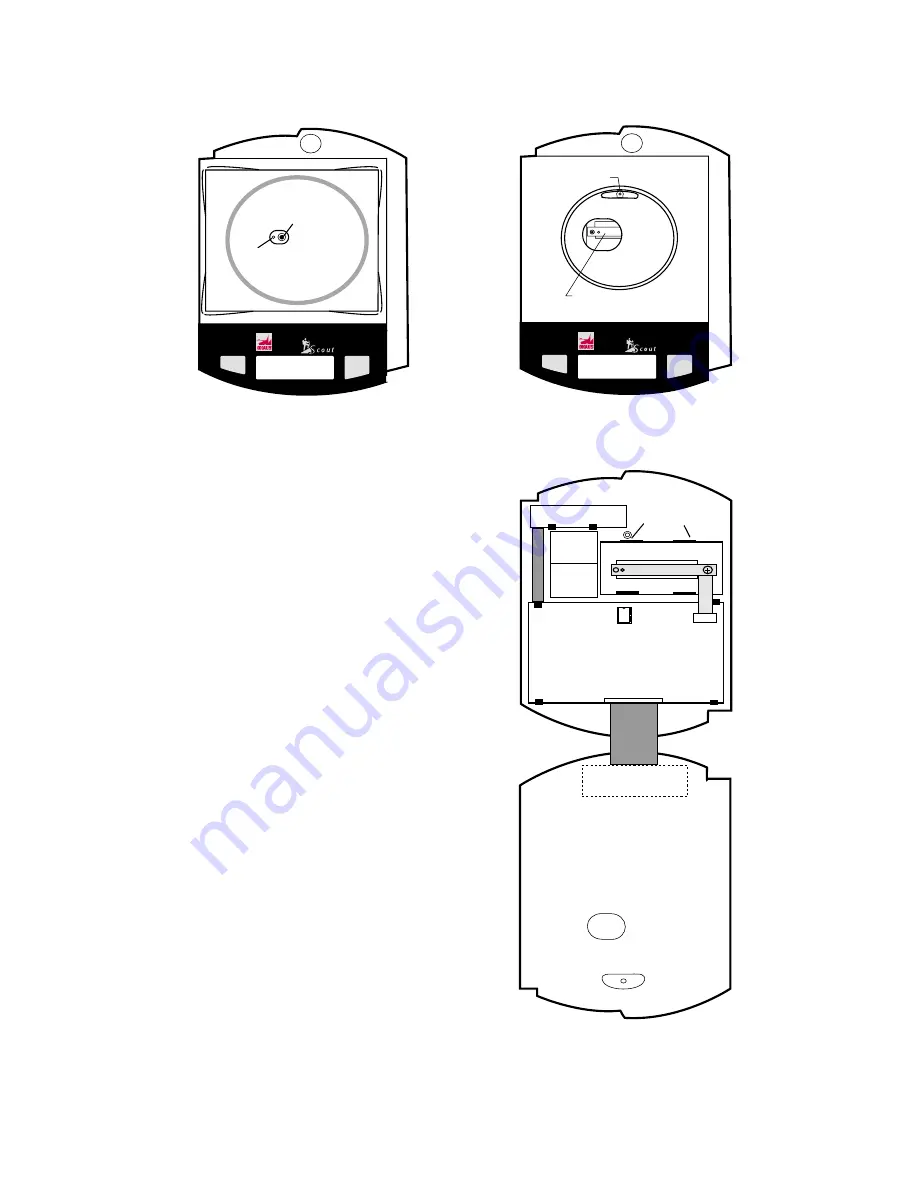
Figure 4-7. Platform Removal.
Figure 4-8. Cover Removal.
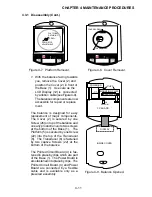
7. With the balance facing towards
you, remove the Cover (2) and
position the Cover (2) in front of
the Base (1). Use care as the
LCD Display (12) is connected
by a ribbon cable (see Figure 4-9).
The balance components are now
accessible for repair or replace
ment.
The balance is designed for easy
replacement of major components.
The Cover (2) is secured by one
Screw (26) on top of the balance and
on early production units, two screws
at the bottom of the Base (1). The
Platform (5) is secured by one Screw
(22) into the top of the Transducer
(8). The Transducer (8) is fastened
by two captive Screws (22) at the
bottom of the balance.
The Printed Circuit Board (4) is fas-
tened in place by clips which are part
of the Base (1). The Power Board is
also fastened into place by clips. The
Printed Circuit Board (4) and Power
Board are connected by a flexible
cable and is available only as a
prewired assembly.
PC BOARD
DISPLAY
POWER BD
BATTERY
COMPARTMENT
TRANSDUCER
MOUNTING PLATE
INSIDE COVER
CLIPS
U6
EEPROM
Figure 4-9. Balance Opened.
Содержание SCOUT
Страница 1: ...OhausCorporation 29HanoverRoad FlorhamPark NJ 07932 0900 ELECTRONIC BALANCES SERVICE MANUAL TM...
Страница 6: ...i v...
Страница 10: ...1 4 CHAPTER 1 INTRODUCTION...
Страница 38: ...5 2 CHAPTER 5 DRAWINGS AND PARTS LISTS...
Страница 39: ...5 3 CHAPTER 5 DRAWINGS AND PARTS LISTS Figure 5 1 Exploded View of Balance 5 3 5 4...
Страница 43: ...SCOUT ELECTRONIC BALANCES P N 300040 010 R1198...
Страница 45: ...e e e...
Страница 47: ......

