


REGULAR MAINTENANCE
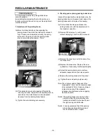
Cutting Edges
Use
Edge 1
25 hrs
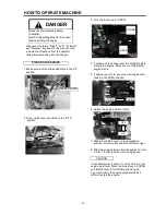
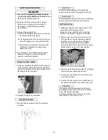
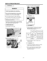
1. Before any inspection or maintenance:
Alternate edge (Turn)
a) Switch Rotor Clutch Lever - OFF
Edge 2
25 hrs
b) Put Brake Handle - UP
Sharpen both edges and use again
c) Switch Feed Switch - STOP
c) Switch Engine Switch - OFF
Note: Sharpen approx. 5 times (300 hrs knife life).
Refer "
Remove & Affix Knives
" to alternate edge.
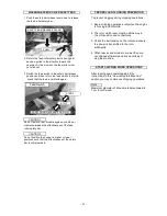
2. ENSURE that machine and engine
parts are not moving and / or hot.
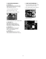
3. WEAR gloves when handling chipper knives
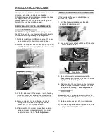
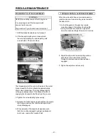
A strip of strong cutting steel on the underside of
Be careful as the knives are very sharp.
the chipping knife from the edge towards the
centre is approx. 13mm wide.
4. REPLACE all covers, guards and housing
parts after inspection.
When sharpening, do not sharpen so much that
width of the strong steel strip becomes less than
5mm. At this point replace the knife.
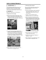
Cutting Edges
Use
Top Edge 1
50 hrs
Alternate edge (Turn)
Top Edge 2
50 hrs
Alternate edge (Flip)
Reverse Top Edge 1
50 hrs
Alternate edge (Turn)
Reverse Top Edge 2
50 hrs
Sharpen all four edges and use again
Note: Can sharpen approx. 3 times = 800 hrs knife
life. Refer to "
Remove & Affix Knives
" to
alternate edges.
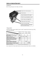
DANGER
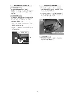
KNIFE BASICS
CHIPPER KNIFE - LIFE AND SHARPENING
COUNTER KNIFE - LIFE AND SHARPENING
IMPORTANT
Top Edge 2
Top Edge 1
Reverse Top Edge 2
Reverse Top Edge 1
Edge 2
Edge 1
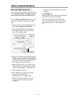
CHIPPER KNIFE
CLEARANCE: 0.5mm
COUNTER
KNIFE
GAUGE (150 MM scale)
GAUGE , 150 MM
FEED
ROLLER
- 23 -