background image

12

Officine Gullo 

ELECTRIC CONNECTION (mod. CVC...)

The appliance is supplied without the connection cable.

To install the power supply cable, proceed as follows:

• 

Disconnect the power supply.

• 

Remove the bottom panel.

• 

Push the connection cable through the cable blocker, connect the conductor wires to the 

corresponding terminals in the junction box and fix them into place.

• 

Block the cable with the cable blocker, and reassemble the front panel. The earth wire must 
be longer than the others so that if the cable blocker should break, it will disconnect after 
the tension wires.

N.B.

 The connection cable must have an adequate section for the power of the appliance and be 

resistant to a temperature of at least 150°C (see technical data table).

EQUIPOTENTIAL

The appliance must be connected to an equipotential system. The connection screw is positioned 

at the back of the appliance and is identified by the symbol  


 .

Attention:

 The manufacturer will neither be held responsible for, nor will give any compensation 

during the guarantee period for any damage caused, and which is due to inadequate installations 
not compliant with the instructions.

CHECKING HEAT OUTPUT

The appliances must be checked in such a way as to verify that the heat output is correct:

• 

The heat output (thermal power) is indicated on the data plate of the appliance.

• 

Firstly, check that the appliance can be used with the type of gas supplied; then 
check that the indication on the plate corresponds to the gas to be used. For con-
verting to another type of gas, check that the type of gas complies with what is 
stated in this instruction manual.

The pressure is read with a gauge (minimum resolution of 0.1 mbar) inserted in the relative 
pressure outlet.
Remove the hermetically closed screw and connect the gauge pipe.
After reading, put back the screw, tightening it hermetically and check for leaks.

Connection for liquid gas G30/G31

The connection pressure for liquid gas is 30 mbar with butane and 37 mbar with propane.
Check the plate, read the pressure and verify that the description of the nozzle installed 
corresponds to the one supplied by the manufacturer.

Connection with natural gas H G20

The connection pressure for natural gas is 20 mbar.
Check the plate, read the pressure and verify that the description of the nozzle installed 
corresponds to the one supplied by the manufacturer.

Содержание CVCS4G

Страница 1: ...INSTRUCTIONS for installation and use PASTA COOKER FOR RESIDENTIAL AND PROFESSIONAL USE CVCS4G CVCS6G CVS4G CVS6G...

Страница 2: ...appliance s maximum power consumption The use of adapters multiple power boards and extension cords is not recommended 8 When not in use switch off the general power supply to the appliance and close...

Страница 3: ...G A 65 635 700 28 79 511 105 35 200 50 285 17 302 25 75 37 377 33 40 400 800 1200 1600 B C A 635 700 635 700 28 511 105 35 200 50 285 17 302 25 75 335 40 40 207 400 800 1200 1600 B C A 635 700 A Data...

Страница 4: ...4 Officine Gullo CVSC4G A Data Plate C Gas Connection ISO 7 1 R1 2GM D Water connection R 1 2GM E Water drainage R 1GF FIG B...

Страница 5: ...5 Officine Gullo CVSC6G A Data Plate C Gas Connection ISO 7 1 R1 2GM D Water connection R 1 2GM E Water drainage R 1GF FIG B2...

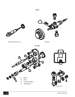
Страница 6: ...6 Officine Gullo FIG C Piezoelectric device Bypass FIG D 2 3 4 1 1 H Injector 1 Bride 2 Pilot 3 Thermocouple 4 Spark plug...

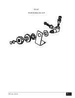
Страница 7: ...7 Officine Gullo FIG E WATER FILLING TAP...

Страница 8: ...gaz Gas solenoid valve Electrov lvula gas 5 Pulsante accensione bruciatori Druckknopf Brennerz ndung Poussoir allumage br leurs Push button starting burner Pulsador encendido quemador 6 Interruttore b...

Страница 9: ...E 15 SPARE PARTS 15 WATER SUPPLY CHARACTERISTICS 15 WATER CONNECTION AND DRAINAGE 15 STARTING UP 16 LIGHTING AND ADJUSTING THE MAIN BURNER MOD CVS 16 OPERATION MOD CVC 16 TURNING OFF THE APPLIANCE 17...

Страница 10: ...sions N B The manufacturer declines any responsibility for direct or indirect damage caused by improper or incorrect installation maintenance or use of the appliance and alterations as in all the othe...

Страница 11: ...latest editions concerned The installation transformation and repair of appliances for professional kitchens as well as removal due to malfunction and the supply of gas may be made only by means of a...

Страница 12: ...te installations not compliant with the instructions CHECKING HEAT OUTPUT The appliances must be checked in such a way as to verify that the heat output is correct The heat output thermal power is ind...

Страница 13: ...urner 9 kW min 3 7 kW Burner Injector 1 100 mm Min output adjustment 1 100 mm Pilot Injector Consumption Primary air h mm 150 85 19 kg h 0 710 20 150 85 19 kg h 0 699 20 230 adjustable 35 m st h 0 952...

Страница 14: ...ew the nozzle and substitute it with the right one see the Technical Data table The main burner does not require any regulation of the primary air SUBSTITUTING THE NOZZLE IN THE PILOT BURNER The flame...

Страница 15: ...and washing up liquid rinsed thoroughly and filled with water up to the level indicated by the mark on the back of the water tub DO NOT START UP THE APPLIANCE WITH THE WATER TUB EMPTY WATER SUPPLY CHA...

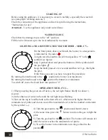
Страница 16: ...w second and then let it go this lights the pilot If the flame goes out you have to repeat the procedure By turning the knob round to the position the burner is at maximum By turning the knob round to...

Страница 17: ...uated below the appliance SAFETY THERMOSTAT MOD CVS Theapplianceisprovidedwithasafetythermostatwhichinterruptsthegasflowifthetemperature goes above the maximum set value When the safety device interve...

Страница 18: ...sed to obtain the special burnishing effect on the burnished brass details in order to avoid spoiling the beauty of the brass with an artificial patina The antique finish of the surface is the result...

Страница 19: ...neutral detergent and where necessary a soft possibly micro fiber cloth Do not use abrasive pads or any other chemical products CLEANING BRUSHED STEEL SURFACES All the brushed steel surfaces should b...

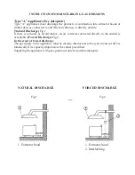
Страница 20: ...no hood as an alternative an air extractor connected directly to the outside is acceptable Forced Discharge Fig 2 In the event of forced discharge The gas supply to the appliance must be directly int...

Страница 21: ......

Страница 22: ......

Страница 23: ......

Страница 24: ...WWW OFFICINEGULLO COM V 2 1 9 17 OFFICINE GULLO S R L via della Torricella 29 50012 Antella Bagno a Ripoli FI Tel 39 055 6560324 621807 Fax 39 055 620670 info officinegullo com en INTERNATIONAL...

Отзывы: