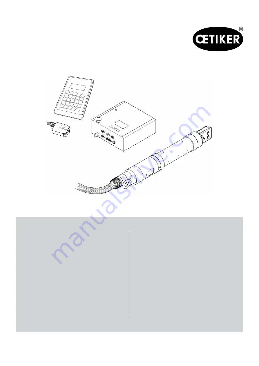
Electronically controlled
pneumatic pincer
OETIKER ELK 02 V2.X
Original instruction manualIssue May 2021
Item no. 08903352OETIKER Horgen, Switzerland
Instruction manual
Страница 1: ...Electronically controlled pneumatic pincer OETIKER ELK 02 V2 X Original instruction manual Issue May 2021 Item no 08903352 OETIKER Horgen Switzerland Instruction manual ...
Страница 2: ... 2 11 2 4 Special safety instructions 2 12 2 5 Safe working practices 2 12 2 6 Modifications changes 2 12 2 7 Qualified personnel 2 13 2 8 Maintenance work 2 13 3 Design of the ELK 02 system 3 14 3 1 Optional extras 3 15 3 2 Design of the HO EL pincers 3 15 3 3 Connections on the ELK 02 control unit 3 16 4 Process description 4 18 4 1 Closing force 4 18 4 2 Procedure 4 19 4 3 Sequence of operation...
Страница 3: ...lly 7 29 7 2 3 Installing the USB driver 7 29 7 3 PC program structure 7 30 8 Structure of the PC program 8 31 8 1 Preparing to read and send data 8 32 8 2 File menu 8 32 8 2 1 Closure data table new 8 33 8 2 2 Pincer type overview 8 38 8 2 3 Backup Restore 8 39 8 2 4 ELK 02 firmware update 8 40 8 2 5 Quit 8 40 8 3 Pincer test 8 40 8 4 Measure 8 42 8 5 Options 8 44 8 5 1 Statistics menu 8 45 8 5 2...
Страница 4: ...ial closure 9 100 9 4 9 Closure step by step 9 103 9 4 10 Closing with hold 9 104 9 4 11 Closure with detect 9 105 9 4 12 Closure with contact detection 9 106 10 Maintenance and repairs 10 107 10 1 General safety instructions for maintenance and repair work 10 107 10 2 Maintenance 10 107 10 2 1 Before maintenance work 10 107 10 2 2 After maintenance work 10 107 10 2 3 Weekly preventive maintenance...
Страница 5: ...2 ELK 02 housing 13 129 13 2 3 Accuracy within the working temperature range 13 129 13 2 4 Temperature 13 129 14 Troubleshooting 13 130 14 1 General notes on faults 13 130 14 2 What to do when 13 130 14 3 Error messages and error correction measures 13 130 15 Checklists repair forms 14 133 15 1 Checklist for ELK 02 control unit 14 133 15 2 Pincer checklist repair form 15 135 16 Warranty conditions...
Страница 6: ...situation Failure to observe this notice will lead to death or serious injury WARNING Hazardous situation Failure to observe this notice may lead to death or serious injury CAUTION Hazardous situation Failure to observe this notice may lead to minor injury NOTICE Information on the avoidance of property damage INFO Information relating to the understanding or optimization of working practices One ...
Страница 7: ... INFO ELK 01 software and data sets cannot be migrated to the ELK 02 All pincer types are stored in the ELK 02 Storage capacity for 99 active program numbers APNs Nominal force input directly on the ELK 02 without PC Closure with detection to prevent double closures Force and gap priority with verification for the qualification Measurement screen can be called directly from the individual closure ...
Страница 8: ...closure data simplified Because of the implementation of DUAL closure and for better overview and easier operation the individual closure data viewing screen has been revised In the closure functions there remain only Force priority Gap priority Dual closure Verification is switched on and off via a þ e g þ Open þ Hold etc The closure function and verification are determined by the pincer type Eve...
Страница 9: ...ok closure OF Open OF SK Closing time between opening closing force OF SS Closing time between opening closing gap OF Z Removal time OS Opening gap OS SK Closing time between opening gap closing force OS SS Closing time between opening gap closing gap OS T Opening gap tolerance pE Compressed air supply pressure pA Compressed air output to pincer S Closure function code for gap priority s Closure f...
Страница 10: ... V2 X 1 Information about this manual Issue 05 2021 08903352 1 10 1 5 Labels on the ELK 02 Fig 1 Labels on the ELK 02 1 Warning labels on the back of the control unit 2 Warning label 3 Risk of crushing 4 Rating plate ...
Страница 11: ...e for the intended purpose also covers observance of this instruction manual and compliance with the technical data Any use not in accordance with the intended purpose is regarded as incorrect Use other than for the intended purpose The ELK 02 has been developed in accordance with the best available technology and is safe for use Residual dangers remain if it is used incorrectly or by untrained pe...
Страница 12: ...tions Only specially trained personnel are authorized to carry out maintenance and repair work on pneumatic equipment Depressurize the machine s pneumatic equipment before starting maintenance or repair work Check hoses for wear as part of the preventive maintenance routine and replace them if necessary 2 5 Safe working practices Before each start of production check the ELK 02 for visible damage ...
Страница 13: ...l data and the following safety rules and regulations Qualified personnel are people who are familiar with setting up assembling commissioning and operating the product and who have the qualifications appropriate to their job role 2 8 Maintenance work The inspection and maintenance intervals specified in the instruction manual must be complied with Maintenance and repair instructions must be follo...
Страница 14: ...m The ELK 02 electronically controlled pneumatic pincer system comprises the following main components Fig 2 Design of the ELK 02 system 1 Status lamp 2 Pre filter 3 Accumulator 4 Control unit 5 Pneumatic pincer EL 6 PC with installed software 7 Closing force sensor SKS 01 8 Calibrator CAL 01 optional extra ...
Страница 15: ...isual detection of OK and NO closures and for the audible detection of NO closures 3 2 Design of the HO EL pincers Fig 3 HO EL pincers 1 Rotary adapter 2 EL trigger unit optional extended trigger not shown 3 Possible mounting surfaces 4 Pincer plate 5 Pincer jaw 6 Grease nipple 7 Union nut 8 Lock nut 9 Pincer body 10 Vent holes 11 START button 12 LED light 13 Suspension loop NOTICE Risk of pincer ...
Страница 16: ...nit please refer to section 13 1 from p 13 116 Fig 4 Control unit connections Item in Fig 4 Name of interface Type use 1 pA Compressed air output to pincer 2 X1 9 pin SUB MIN D male Pincer connection 3 X2 15 pin SUB MIN D HD male Inputs outputs 4 X3 9 pin SUB MIN D female Computer connection RS232 Connection CAL 01 RS232 5 X20 25 pin SUB MIN D male Inputs outputs 6 X5 6 7 Option ...
Страница 17: ...nal bus interface 9 Optional bus interface 10 Vent 11 Vent 12 3 pin IEC connector male 13 On Off switch 14 pE Compressed air supply pressure see safety notice below Table1 Connections to the control unit NOTICE Risk of pincer jaw damage When using the HO 10000 pincer model make sure that the compressed air supply pressure pE does not exceed 5 bar ...
Страница 18: ...then be used if required for recording the closure data and for inputting the nominal force Contact detection The contact detection function determines the contact position of the corresponding clamp with the material being clamped at the start of compression 4 1 Closing force OETIKER clamps and Low Profile Clamps must be closed with a recommended and uniform closing force force priority This resu...
Страница 19: ...eter to the required size for engagement Depending on the product the clamp is either engaged automatically or by applying contact pressure on reaching the engagement position On reaching the predefined parameter values the jaws on the pincer head are opened INFO The closure sequence is dependent on the closure data and on the predefined system data It is initiated by pressing the START button for...
Страница 20: ... level 4 3 1 Test level Fig 8 The test level ELK 02 einschalten System Test Regelungseinheit und Peripherie bei erreich Schließungen gem System Einstellung Zangentest Aufforderung extern gem System Einst über V24 X3 CAL 01 PC keine Autorisierung notwendig FUNKTION Zangentest APN Autorisierung Zangentest Fehlermeldung F1 F4 F15 Fehlerbehebung Fehler Quittierung gem System Einstellung Überspringen S...
Страница 21: ... at least once per shift minimum daily Furthermore a pincer test is mandatory in the event any pincer components are replaced To maintain consistent pincer force sufficient compressed air pressure and volume must be provided After pincer test Oetiker recommends verifying the closing force as a secondary validation It is essential to ensure clamp closures are not conducted in pincer test mode ...
Страница 22: ...ig 9 The closure level Kraft Weg Prior oder Dual mit oder ohne Halten detektieren Kontakt detektieren mit ohne verifizieren Start extern Vorwahl APN extern NO Fehlermeldungen während der Schließung F1 F24 Datenprotokoll Messergebnisse Fehlermeldungen chaotisch Taste Zange OK singulär sequenziell ...
Страница 23: ... 3 m optionally 6 m or 12 m When the pincer Fig 10 2 is not in use store it in a plastic holder Fig 10 1 for example Make sure that the bending radius of the corrugated hose Fig 10 3 is not less than 50 mm when in use Warning Compressed air must be clean and dry free of oil and moisture Fig 10 Connecting the ELK 02 1 Holder for pincer plastic recommended supplied by others 2 Pincer 3 Corrugated ho...
Страница 24: ...ver lift the pneumatic pincer by the corrugated hose INFO To optimize the closure of OETIKER clamps and Low Profile Clamps we recommend using a floating mount for OETIKER EL T pincers that are mounted in a jig Appropriate devices are available as an option The compressed air supply pressure must be between 4 and 10 bar 6 bar is recommended For the HO 10000 this must not exceed 5 bar A cutout mecha...
Страница 25: ... the START button Fig 6 3 is pressed or when a start is initiated by an external control Do not hold the pneumatic pincer in the clamping area 1 Switch off the ELK 02 control unit 2 Shut off the compressed air supply 3 Loosen the lock nut Fig 11 1 4 Loosen the union nut Fig 11 2 slightly 5 Rotate the pincer head Fig 11 3 into the desired position 6 Tighten the union nut Fig 11 2 and secure with th...
Страница 26: ...ror message is output During operation the vent holes Fig 12 2 on the pincer body Fig 12 1 must not be blocked Make sure that any fixture that is fitted does not block the vent holes Fig 12 Vent holes 6 2 Switching on the ELK 02 1 Switch on the ELK 02 using the On Off switch Fig 13 2 on the control unit Fig 13 1 After switching on a system check is performed If all the checks are OK FUNCTION appea...
Страница 27: ...stallation or on initial startup please contact your system administrator ELK 02 can be installed in parallel with an existing ELK 01 ELS 01 program The program CDs or USB stick are full program versions and contain the following PC software Process data pincer related data System settings Clamping data default force and gap data USB driver Installation see section 7 2 3 p 7 29 Languages file Righ...
Страница 28: ...ollowing descriptions assume a basic knowledge of the Windows operating system 7 2 1 Installing the program automatically 1 Close all open applications 2 Place the CD in the CD ROM drive After a few seconds the installation instructions will be displayed on the screen Fig 14 Start menu 3 Follow the instructions on the screen ...
Страница 29: ...up drive name of CD ROM drive e g D Intsetup 4 Click OK 5 Follow the instructions on the screen 7 2 3 Installing the USB driver INFO The USB driver does not install automatically 1 Start installation by double clicking on the exe file in the USB Driver on the installation CD 2 Select 32 bit or 64 bit according to the computer configuration Windows 7 If an old USB driver is already installed on a W...
Страница 30: ...cation related changes to system settings for parameterizing inputs and outputs operating modes and system constants Display of a measurement screen for viewing closing forces and gap values after a closure Statistics screen for reading the closure data and confirmation of completed pincer tests Languages file When the PC program is started a safety instruction message is displayed Please notice F...
Страница 31: ...enu Submenus File New closure data table Open closure data tables Pincer type overview Backup Restore Quit Pincer test Request pincer test Authorize pincer test Nominal force entry Measure Options Interface Force display PC Statistics Process data Password Screen scaling System settings Languages Help Table2 Main menus in the PC program ...
Страница 32: ...INFO If no data cable is connected or the ELK 02 is not powered up the message Device not responding will be displayed 8 2 File menu Fig 17 File menu Submenu Description New closure data table Creates a new closure data table Open the closure data tables Opens the existing closure data table overview Pincer type overview Opens a table showing all the pincer types available in the ELK 02 software B...
Страница 33: ...hich is displayed in the closure data table overview You must input a new file name in order to save it Open Opens an existing closure data table Save Saves changes to the current closure data table under its existing name If it is a new table you will be prompted to input a name Save as Saves the current closure data table under a name and path of your choice and copies it as a current table to t...
Страница 34: ...l view Opens a individual closure data view to create closure data Condition At least one individual closure data view view must have been created Copy Copies the currently highlighted closure data table to the clipboard Insert Inserts a individual closure data view from the clipboard You can insert the same individual closure data view from the clipboard more than once Delete Deletes the currentl...
Страница 35: ... order Unsorted Restores the chronological order of the created clamp individual view Table6 Submenus in the File menu New closure data table View Sequence menu INFO There must be at least two individual closure data view in the stored closure data table Define sequence A closure data table can have up to 99 individual closure data view These max 99 individual closure data view can be defined as a...
Страница 36: ...rom 4 to 30 but 1 to 3 will be retained send to the ELK 02 to update it Fig 22 File menu New closure data table Sequence Submenu Description Send Sends a sequence to the ELK 02 When the transfer has been completed the window closes Read Reads a sequence from the ELK 02 When the transfer has been completed the window closes OK Assigns the defined sequence table to this grouped closure data overview...
Страница 37: ... the ELK appears in the confirmation window YES Adds the data sets to the data in the ELK 02 and overwrites existing data sets with the same APN number NO Deletes the existing data sets in the ELK 02 and copies the current table Read individual data set from ELK 02 You are prompted to specify which data set is to be read back When you input the APN this data set is read back from the ELK 02 If the...
Страница 38: ...d protected Send command copies the pincer type data stored in the ELK 02 PC software to the ELK 02 Fig 24 Pincer type overview menu Button Description Send Sends all the pincer types shown in the overview to the ELK 02 Cancel Takes you back to the File menu Bar Displays the progress bar Date Shows the date on which the pincer type file was created or modified Table9 Submenu in the File menu Pince...
Страница 39: ...or restore file Start backup Start restore The selected file is saved backup Enable to activate see section 8 5 2 Inputting the password to edit user rights Cancel Takes you back to the File menu Table10 Submenus in the File menu Backup Restore Backing up restoring data 1 Carry out the preparatory steps see section 8 1 p 8 32 2 In the Select file input box select the desired backup or restore file...
Страница 40: ...t Fig 26 Pincer test menu Submenu Description Request pincer test Opens the FUNCTION screen in the ELK 02 in which the pincer test can be requested Authorize pincer test Allows a pincer test to be performed Authorization is necessary if the pincer test is requested after one of the following events after a pincer change on reaching a predefined number of closures via the External bit pre selection...
Страница 41: ...essure and volume must be provided After pincer test Oetiker recommends verifying the closing force as a secondary validation It is essential to ensure clamp closures are not conducted in pincer test mode The force correction can be input in various ways via input in the ELK 02 display under Force test Correct nominal force using the CAL 01 see CAL 01 instruction manual via the PC the calculated f...
Страница 42: ...osure function After the closure the status is set to OK or to NO with the error message Fig 28 Measure menu Output error Description Closure function F Force priority with verification f S Gap priority with verification s D Dual closure with verification d Status OK the closure was successful NO an error occurred see below Error The error message is displayed see Table13 Save data in file Saves t...
Страница 43: ...he save operation If the screen is not visible the data will not be saved Error Output X2 Output X20 F04 OS ERROR NO à H NO à H F05 SK ERROR NO à H NO à H F06 SS ERROR NO à H NO à H F07 SK SS ERROR NO à H NO à H F09 HK ERROR NO à H NO à H F10 HS ERROR NO à H NO à H F11 HK HS ERROR NO à H NO à H F12 VK ERROR NO à H NO à H F13 VW ERROR NO à H NO à H F14 VK VW ERROR NO à H NO à H F16 CANCEL PROCESS N...
Страница 44: ...stics The values for the closure process that are saved in the ELK 02 can be read for purposes of statistical analysis The following screens can be used here ELK data see p 8 45 NO closures see p 8 47 Pincer test see p 8 48 Process data Process data is password protected pincer type data which is only accessible to OETIKER personnel Password To change the password access service mode or input user...
Страница 45: ...d after how many closures Total number of closures Shows the number of closures since the date of manufacture of the ELK This value cannot be reset Total number of NO closures Shows the number of NO closures since the date of manufacture This value cannot be reset Maintenance requirements Last maintenance at Shows the number of closures at the last maintenance Carried out since Shows the number of...
Страница 46: ...is no limit to the number of times the reminder can be acknowledged but the reliability of a closure may be compromised Print Starts printout of the ELK data Read Reads all data from the ELK 02 ELK data NO closures and pincer test Cancel Takes you back to the Options menu Table15 Input boxes and checkboxes in the ELK data menu Reading ELK data 1 Carry out the preparatory steps see section 8 1 p 8 ...
Страница 47: ...Deletes the NO closures Division deleted on Date of deletion At closures Number of NO closures for which the division was deleted Print Starts printout of the NO closures Read Reads all data from the ELK 02 ELK data NO closures and pincer test Cancel Takes you back to the Options menu Table16 Input boxes and checkboxes in the NO closures menu Read NO closures 1 Carry out the preparatory steps see ...
Страница 48: ...rmed Pincer type Shows the pincer type for each closure Force calibration There are two methods of force calibration Force calibration with constant target value setting Force calibration with constant nominal force Force setting Shows the closing force set for the pincer type in the pincer test force test Nominal force input The calculated value of the closing force that was input Print Starts pr...
Страница 49: ...e section 8 1 p 8 32 2 Click the Read button 8 5 2 Password menu Fig 33 Options menu Password The default password for accessing the system settings is ELK02 The system settings password can be changed at any time 1 Input the old password ELK02 2 Input a new password 3 Input the new password again as verification 4 Click OK to confirm ...
Страница 50: ... the password 2 Click OK to confirm Inputting the password for service mode 1 Input the password 2 Click OK to confirm Inputting the password for service mode 1 Input the password 2 Click OK to confirm INFO These user rights remain enabled even after quitting the ELK 02 program To disable them reset deactivate the checkboxes ...
Страница 51: ...enu Description Display factory settings Displays the default factory settings Send factory settings to ELK 02 Sends the factory settings data to the ELK 02 Read settings from ELK 02 Reads data from the ELK 02 Load settings from file Loads the user defined file Table18 Submenus in the System settings menu General information on function specific screens in the system settings Functions are switche...
Страница 52: ...in accordance with the closure function has been initiated Fig 36 START system settings Input box checkbox Description Start acknowledgement via START button or external control START button External control START button or external control START button in the trigger unit EL or in the extended trigger ELT External control via the X2 or X20 interfaces Start only via START button Start only via X2 ...
Страница 53: ...cer jaws open immediately and F16 CANCEL PROCESS appears in the display A pulse of 20 ms at the START button or via the interface X2 Start Acknowledge or X20 Enable and Start pulse of 20 ms see Start acknowledgement via START button or external control in the table above NOTICE When the OETIKER ELK 02 is set to Impulse operation you must make sure that it is impossible for persons to reach the dan...
Страница 54: ...OETIKER ELK 02 V2 X 8 Structure of the PC program Issue 05 2021 08903352 8 54 Fig 37 Safety instruction START system settings ...
Страница 55: ... signal one pulse on initiation of start function NO signal one pulse on initiation of start function LED function one pulse on initiation of start function The delay time between the initiation of the start function and the closing movement of the pincer jaws determines the longest pulse time for the OK or NO signal or the LED function System settings for the OK signal This menu defines the respo...
Страница 56: ... on the ELK 02 display or After a closure and display of the following messages on the ELK 02 display the ELK 02 is ready for closure SS SK OK or SS SK OK toggling to VW VK The output can be supplied as continuous signal one pulse 10 1000 ms no output NOTICE If the X20 interface is activated there is an option to switch between the X2 and X20 interface in the Other system settings a separate outpu...
Страница 57: ... on opening the pincer jaws from SS SK VW to fully open the pincer head reaches the OS defined at the start time within its tolerance OS T a continuous signal is output until the next start factory setting one pulse If on opening the pincer jaws from SS SK VK to fully open the pincer head reaches the OS defined at the start time within its tolerance OS T one pulse is output range 10 1000 ms no out...
Страница 58: ...a sequence in the last pressing operation and the OS assigned to the last pressing operation is reached within its tolerance OS T a continuous signal is output until the next start factory setting Pulse If the pincer jaw opens from SS to fully open in a sequence in the last pressing operation and the OS assigned to the last pressing operation is reached within its tolerance OS T one pulse is outpu...
Страница 59: ...e end of the sequence If the OS is reached within its OS T one pulse is output Default 500 ms range 10 1000 ms One pulse on reaching the HS HK Condition The Hold function has been pre selected If the HS is reached within the HS T and the HK within the HK T one pulse is output Default 500 ms range 10 1000 ms Table20 System settings for the OK signal INFO The signals are added together if multiple f...
Страница 60: ...One impulse when closure starts One pulse is supplied when closure starts Factory setting 500 ms range 10 to 1000 ms After each NO continuous signal Continuous signal until the next start If the OS defined at the start time is reached within its tolerance OS T on opening the pincer jaws from SS SK VW to fully open a continuous signal is output until the next start factory setting NOTICE The openin...
Страница 61: ...T on opening the pincer jaws from SS SK VW to fully open one pulse is output Default 1000 ms range 10 1000 ms NOTICE The opening gap OS is approached again only after the acknowledgement time has elapsed No output Data output at X3 on error Data output at X3 on error see p 13 124 Table21 System settings for the NO signal INFO The signals are added together if multiple functions are active ...
Страница 62: ... LED function Input box checkbox Description One impulse when closure starts The LED lights up with one pulse when closure starts Factory setting 500 ms range 10 to 2500 ms After each NO continuous signal Continuous signal until the next start If the OS defined at the start time is reached within its tolerance OS T on opening the pincer jaws from SS SK VW to fully open the LED lights up until the ...
Страница 63: ...in its tolerance OS T on opening the pincer jaws from SS SK VW to fully open the LED lights up for the length of one pulse Default 1000 ms range 10 1000 ms NOTICE The opening gap OS is approached again only after the acknowledgement time has elapsed No output Table22 System settings for the LED signal INFO The signals are added together if multiple functions are active ...
Страница 64: ...rms a complete closing sequence when a start is initiated e g OS SS OF OS Closure mode in which closure has to be initiated separately for each step Outputs OK signal pulse on completed step output at X2 X20 Data output at X3 On completed step With value output NOTICE Only in step by step mode When a closure step is completed within tolerance this is recorded as OK e g OS OK and pulses can be outp...
Страница 65: ...allows to choose from two options when switching on the ELK02 pincer test APN ZT pincer test see Table27 page 9 74 ELK02 Power ON without function selection direct to active APN Pincer test mode which directly opens the active APN when switching on the ELK02 Pincer test prompt by external bit pre selection at X2 The pincer test is activated via the X2 interface Default bit 10 range bit 10 15 Activ...
Страница 66: ...st large gap test small gap test Check values for plausibility The following checks are performed during the pincer test Stiffness of pincer Measuring device check in force test Correct gauge sequence If a fault occurs the error message F16 CANCEL PROCESS appears on the ELK 02 display Princer test with constant nominal force The force test is performed at a uniform constant nominal force the inter...
Страница 67: ...OETIKER ELK 02 V2 X 8 Structure of the PC program Issue 05 2021 08903352 8 67 Fig 44 Safety instruction system settings for pincer test ...
Страница 68: ...al output Negates the OK output logic L Low becomes H High H High becomes L Low Negation of NO signal output Negates the NO output logic L Low becomes H High H High becomes L Low pincer remains closed in case of NO At the end of the closure the system checks whether the closure data is within tolerance For NO closures the pincer remains closed Outputs X2 NO becomes H High X20 Busy becomes H High X...
Страница 69: ...Data output at X3 when ready for closure p 13 122 Display time 1 Display time 2 If more than one display is needed e g with verification or with sequential pressing the display is switched over The display times can be adjusted Closures with verification Display time 1 Display time for the verification data VW VK or next APN range 500 to 5000 ms Display time 2 Display time of the closure data SS S...
Страница 70: ...mation send to Oetiker for maintenance This message is acknowledgeable to do further closures Information Under personal responsibility this number of closures can be changed or the feature disabled by setting it 0 zero Repetition After every 1 000 closures the message F24 MAINTENANCE reappears on the ELK 02 display and is acknowledgeable see safety instruction Fig 46 Table25 Other system settings...
Страница 71: ...equired for access If changes have been made to the system settings you are given the option of saving the settings If no changes have been made to the system settings the program returns directly to the main window If changes to the system settings are to be saved a Save dialog window opens see Fig 47 Fig 47 Save system settings dialog window ...
Страница 72: ...equired 2 Click OK to confirm The PC software switches to the selected language 8 5 6 Help Contact addresses for OETIKER branches see also the back cover of this manual Notes on the program Input box checkbox Description Status of process data Date Shows the date on which the pincer type file process data file was created or modified ...
Страница 73: ...ing information error messages etc 2 1st 3rd line text depending on the content only one line may be displayed but in a larger font 3 Button functions A to D various functions are depicted in symbol form here and initiated by the buttons below 4 4 Pushbuttons corresponding to button functions A to D in the display Table26 Display The key functions and the print buttons can optionally be disabled i...
Страница 74: ...N Active program number direct selection of the APN Takes you to the Correct nominal force submenu Pincer test request ZT takes you directly to the pincer test bypassing the Function menu Scrolls down through display texts Scrolls up through display texts Takes you one step back OK confirms an input Cancel aborts an input Table27 Symbols and abbreviations in the display 9 2 Menu structure Menu nav...
Страница 75: ...e Pincer selection HO xxxx xxxx F02 NO PINCER Connect pincer Measuring system defective F03 MEASURING SYSTEM Tighten connector screws Pincer defective ELK 02 Firmware xxxxx Creation date xxxxx APN 2s APN 4s Parameter input Brightness Contrast Languages Info Intake pressure Pincer type Brightness XX Contrast XX Legend OK Cancel Acknowledge Back up down Nominal force correction Pincer test SKS Pince...
Страница 76: ...TAKE PRESSURE F02 NO PINCER F03 MEASURING SYSTEM Function Function selection Pincer test Pincer selection HO xxxx xxxx ELK 02 Firmware xxxxx Creation date xxxxx 2s APN 4s Pincer test Friction test APN Back if APN and APN 4s do not appear on this screen Fig 51 Sequence of operations at the test level ELK 01 mode Function selection is depending on the selected system settings ...
Страница 77: ...PN Closure Back to the function Back to the function Start friction force gap test START button 2 s 4 s 100 ms 4 s Start 100 ms apply force 2 s 2 s 2 s a Scroll mode 100ms b Function 2 s X20 inputs Function 2 s 4 s 4 s Apply force 2 s 2 s 2 s a Scroll mode 100 ms b Function 2 s Start and enable 100 ms 100 ms Pincer test 100 ms X2 input Start 2 s 4 s 100 ms 4 s Start 100 ms apply force 2 s 2 s 2 s ...
Страница 78: ...th mandatory pincer test b Optional setting Power On operator may select start up mode pincer test or closure level APNs Prerequisite The pincer has not been changed c Optional setting Power ON without pincer test Direct start in closure level APNs NOTICE In order to ensure uniform and reproducible process quality it is mandatory to perform an assembly tool pincer test at least once per shift mini...
Страница 79: ...brator CAL 01 see the instruction manual for the CAL 01 The pincer test can be requested via the following interfaces via the External bit pre selection interface X2 e g bit 10 via the Pincer test interface X20 Furthermore the pincer test can be requested manually from the APN mode menu using the step back button on the ELK control unit by the internal closure counter if Pincer test after number o...
Страница 80: ...V2 X 9 Menu navigation in the ELK 02 Issue 05 2021 08903352 9 80 The following checks are made during the pincer test intake pressure F01 loss of pressure F23 incorrect missing or out of sequence measuring devices F16 ...
Страница 81: ...d the calibration of the open and closed pincer jaws Fig 53 Sequence of operations in the friction test External interface X2 X20 can be selected via the System settings Other menu 1 X2 Start Acknowledge 2 s X20 Function 2 s 2 can be disabled in the system settings 3 X2 Start Acknowledge pulse X20 Enable and Start pulse 4 X2 Start Acknowledge 4 s X20 Enable and Start 4 s ...
Страница 82: ...e message F25 MAX 20 CLOSURES appears on the ELK 02 display When the message is acknowledged a mandatory pincer test is required again INFO This monitoring prevents the operation of the ELK 02 in pincer test mode Fig 54 Sequence of operations in the force test External interface X2 X20 can be selected via the System settings Other menu 1 X2 Start Acknowledge pulse X20 Enable and Start pulse 2 X2 S...
Страница 83: ...r geometry Four gap tests have to be performed using the test gauge corresponding to the predefined display sequence Fig 55 Sequence of operations in the gap test External interface X2 X20 can be selected via the System settings Other menu 1 X2 Start Acknowledge pulse X20 Enable and Start pulse 2 X2 Start Acknowledge 4 s X20 Function 4 s ...
Страница 84: ...OETIKER ELK 02 V2 X 9 Menu navigation in the ELK 02 Issue 05 2021 08903352 9 84 9 4 The closure level Fig 56 Sequence of operations at the closure level ...
Страница 85: ...nctions can be defined in the System Settings PC program and are sent to the ELK 02 by data exchange singular closure chaotic closure sequential closure Step by step INFO Once the transfer has been performed successfully the ELK 02 operates autonomously without a PC connection The closure sequence with the closing forces and closing gaps and their chronological closing order is defined in the Indi...
Страница 86: ...n APN Active program number max 99 Text For a note about the APN Clamp type For inputting the clamp type Pincer type Selects the pincer type to be used for this closure The most suitable closure function is suggested You can however change it if you wish The characteristic pincer values e g closing gaps and forces verification data and times are also set to default values The type and number of pi...
Страница 87: ...or message Open OF Pincer jaws are fully open Opening gap OS Distance between the open pincer jaws clear width mm Opening gap tolerance OS T The opening gap tolerance to be monitored mm Removal time OF Z The removal time between Pincer jaws fully open again OF and Closing to opening gap OS can be defined Hold disabled No hold function Hold enabled With hold function Holding gap HS Dimension requir...
Страница 88: ...S T The closing gap tolerance to be monitored Closing force SK Force on the closed clamp NOTICE It is critical to use the clamping force established for the clamp together with the specific application Closing force tolerance SK T The closing force tolerance to be monitored Times Closing time OF SK OS SK HS SK for force priority Closing time between open OF and reaching the closing force SK Closin...
Страница 89: ...rance VK T The verification force VK tolerance to be monitored Time Verification force holding time VK HZ Holding time for the verification force VK Read disabled Reads closure data back from the ELK 02 Send enabled Sends closure data to the ELK 02 Measure VW Opens the Measurement screen to display the closure values Click OK to return to the individual closure data view OK VW T Copies the values ...
Страница 90: ...on OF The pincer jaws must be open OF in order for a closure to be initiated When a START is initiated depending on the Start definition see START system settings p 8 52 the pincer jaws close for the closing time OF SK to the pre selected closing force SK Once the closing force is reached the closing force holding time SK HZ starts Immediately before the end of the closing force holding time SK HZ...
Страница 91: ...ing gap holding time SS HZ the pincer jaws are opened The output OK NO is supplied respectively when the pincer jaws have opened OF or if the opening gap OS is too small Advantage Positioning to an exact closing gap with the predefined closing force SK as the closing force restriction Disadvantage For physical and control technology reasons a slow time must be chosen for the closing time from the ...
Страница 92: ... NO signal p 8 60 Close pincer jaws from the OPENING GAP position OS The pincer jaws must be in the opening gap position OS within the opening gap tolerance OS T in order for a closure to be initiated When a START is initiated depending on the Start definition see START system settings p 8 52 via the Start button or the external X2 X20 interface the pincer jaws close and establish the pre selected...
Страница 93: ...ity to gap priority The changeover force UK must be up to approx 10 less than the force required to achieve the closing gap SS The value set for the closing force SK limits the actual closing force value during closure The value set for the closing force SK should be at least 30 greater than the anticipated value of the closing force SK so as to obtain sufficient control freedom Depending on the c...
Страница 94: ...not detected the pincer jaws close until they reach the closing gap SS minus the SS T value or until they reach the preset closing force SK Then the pincer jaws open with the error message F17 NOT ENGAGED If the Low Profile Clamp engages the system switches immediately to the verification force but the pincer jaws remain in frictional connection with the Low Profile Clamp in order to ensure a secu...
Страница 95: ...erification force VK At the end of the verification force holding time VK HZ the system checks that the verification force VK is within the verification tolerance VK T and that the verification value VW is within the verification value tolerance VW T The pincer jaws are then opened When the pincer jaws are fully open OF the message OK or NO is output depending on the OK NO definition see System se...
Страница 96: ... on initiation of start function setting see System settings for the NO signal p 8 60 LED function setting one pulse on initiation of start function setting see System settings for the LED signal p 8 62 The delay time between the initiation of the start function and the closing movement of the pincer jaws determines the longest pulse time for the OK or NO signal or the LED function Initiation take...
Страница 97: ...ng at the pincer jaws of the pincer head In pulse mode the closure sequence can be initiated by means of transient external signals and or by pressing the Start button In pulse mode stay clear of the pincer jaws during the closure sequence In addition to the instructions in the manual the generally applicable legal and other binding regulations governing accident prevention and other generally rec...
Страница 98: ...equence Send closure data for up to 99 APNs PC program Close data table Send individual closure data view or Data exchange Send table to ELK 02 Select an APN 1 In the ELK 02 display select Function APN In the Current APN display select APN In the Select APN display use the q p buttons to select the APN you want and confirm with ü or 2 Select an APN externally Fig 67 Fig 66 ...
Страница 99: ...end multiple sets of APN closure data in any sequence and perform any number of closures Sequence Send closure data for 1 to 99 APNs using the PC program via the ELK 02 display see section 9 4 6 Singular closure Select an APN see section 9 4 6 p 9 98 Example Setting bits 3 1 4 2 to select closure data APNs Fig 68 ...
Страница 100: ...t least 2 99 APNs using the PC program Create a sequence 1 In the Closure data table open the Sequence menu see Sequence menu p 8 35 2 Assign any APN from 1 to 99 to the 30 possible closures The sequence ends with the closure in which APN 0 is selected 3 Send the sequence to the ELK 02 INFO The order of the APNs determines the sequence No APNs may be selected at the X2 X20 inputs Fig 69 Sequential...
Страница 101: ...e APNs determines the sequence example 1 Perform the first closure APN3 2 If OK continue with the second closure APN1 3 If NO you must repeat the APN until an OK message is received 4 Perform closure of the last APN Depending on the setting in the System settings for the OK signal menu see p 8 55 a continuous signal a pulse or no output appears at the end of the sequence Example Sequential closure...
Страница 102: ...only in sequential closure with an active opening gap OS It is the time between the last opening to OF fully open and closing to the new opening gap OS The removal time to closing to the OS is assigned to the corresponding APN INFO A removal time OF Z is necessary if the next APN has a smaller opening gap OS than previous APNs Fig 71 ...
Страница 103: ... from verify VW VK to open OF 1 from open OF to the opening gap OS On reaching the hold close and verify position the measured values HK HS SS SK or VW VK are continuously displayed on the ELK 02 display Sequence 1 On the PC program select Options System settings Operating mode Step by step radio button see System settings for operating modes p 8 64 2 Click the Send button The values are sent to t...
Страница 104: ...n a Start is initiated Start definition see section 9 4 5 page 9 96 the pincer jaws close until they touch the clamp ear The force acting on the ear is defined in the holding force HK On reaching this position the system checks that the holding gap HS is within its holding gap tolerance HS T and that the holding force HK is within its holding force tolerance HK T At the same time the measured HK a...
Страница 105: ... NO à H Using the X20 interface 1 Energize with Reset 2 The pincer jaws open System error à H Error message F19 RESET CANCEL is displayed 9 4 11 Closure with detect Function Detection identifies a second closure on the same clamp or Low Profile Clamp and reports it as NO Sequence During the closure operation on passing the detection gap DS the system checks whether the actual detection force DK is...
Страница 106: ...easured contact gap KS distance between the pincer jaws on reaching the predefined contact force KK in relation to the particular application Depending on the chosen contact force KK the material being clamped may already have been compressed This can lead to inaccuracies in determining the contact gap KS Corresponding clamp products are secured with a transit lock to prevent them from opening acc...
Страница 107: ...ded and pull the main plug out of the electrical outlet Following initial commissioning the ELK 02 unit should be cleaned daily or weekly depending on the degree of soiling Never immerse the ELK 02 in water or other liquids 10 2 Maintenance 10 2 1 Before maintenance work WARNING Danger of death from electric shock Touching live parts can result in death Pull the main plug out of the electrical out...
Страница 108: ...jaws Fig 74 2 for wear and chipping at the clamping points and replace if necessary see tools catalog for item number 4 Check the pincer and control unit for mechanical damage 5 Replace defective parts Fig 74 Lubricating the pincer head 10 2 4 Annual preventive maintenance jobs When the OETIKER EL T electronically controlled pneumatic pincer is in regular use we recommend an annual service Please ...
Страница 109: ...an be found in the tools catalog Changing the pincer jaws HO pincers There is a number engraved on the pincer jaws You can use this number to order a pincer jaw replacement kit see also the tools catalog Only fit the designated pincer jaw type in the pincer head NOTICE Damage to the pincer from third party parts Only use original OETIKER pincer jaws Only fit the designated pincer jaw type in the p...
Страница 110: ...ig 76 3 The plunger Fig 76 5 and plunger piston Fig 76 7 remain in the pincer body Fig 76 3 5 Remove the two retaining rings Fig 77 9 on the pincer head Fig 77 6 on the grease nipple side Do not push the pins back Fig 77 10 6 Unscrew the two hex nuts Fig 77 8 from the hex bolts Fig 77 11 7 Remove the pincer plate Fig 78 12 Fig 76 Separating the pincer head from the pincer body Fig 77 Dismantling t...
Страница 111: ...aw replacement kit with RENOLIT LX EP 2 grease RENOLIT Duraplex EP 2 and install 10 Mount the pincer plate Fig 78 12 Guide the cover plates on each side Fig 79 15 into the grooves Fig 79 16 in the pincer plate 11 Check that the pincer jaws Fig 79 13 are moving freely 12 Screw the pincer head Fig 76 6 onto the pincer body Fig 76 3 and secure with the lock nut Fig 75 1 The plunger Fig 76 5 must be c...
Страница 112: ...and cause injury if the pincer head is not mounted Never operate the pneumatic pincer unless the pincer head is mounted INFO Each pincer body is compatible with different pincer heads The type designations can be found in the tools catalog Scope of supply of a pincer head set Lip seal Fig 80 1 Piston ring with plunger piston Fig 80 2 Pincer head Fig 80 3 Wedge Fig 80 4 Compression spring Fig 80 5 ...
Страница 113: ...Lubricate the plunger piston Fig 81 4 plunger Fig 81 5 piston ring Fig 81 8 and lip seal Fig 81 3 from the new piston head set and mount them in the piston body Piston ring Fig 81 8 and lip seal Fig 81 3 with RENOLIT IPR 2 OETIKER item no 08901485 Plunger Fig 81 5 with RENOLIT LX EP 2 RENOLIT Duraplex EP 2 OETIKER item no 08901490 NOTICE Damage during installation Be careful not to damage the pist...
Страница 114: ... remain out of service for an extended period it must be decommissioned Disconnect the pneumatic and electrical plug connectors on the ELK 02 Clean the ELK 02 pneumatic pincer before putting it into storage Replace defective parts Store the ELK 02 in a clean dry location and protect from dust 11 2 Recommissioning Please refer to the HO pincer instruction manual for details of the commissioning pro...
Страница 115: ...Dispose of packaging materials in accordance with local regulations The unit all replacement parts and in particular used operating fluids or other environmentally polluting substances must be disposed of by specialist firms in accordance with applicable statutory regulations ...
Страница 116: ...es Fig 82 Control unit connections 13 1 1 Main plug see Fig 82 8 WARNING Electric shock if PE conductor protective earth conductor not fitted The main power supply must always be protected with a PE conductor 3 pin IEC connector male Operating voltage 85 265 V 47 63 Hz Power consumption 30 VA INFO 10 A backup fuse recommended ...
Страница 117: ...rt Acknowledge bits 1 to 15 Opto decoupled inputs dedicated GND PIN 15 for all bits Nominal value DC 24 V Signal 0 0 5 V Signal 1 15 30 V 100 ms for start Input current 10 mA at 24 V Outputs OK NO digital Output data digital Opto decoupled outputs dedicated GND PIN 5 for OK NO Operating voltage UB DC 24 V max 30 V Output for connecting lamps relays etc Output current IA X2 1 or X2 4 100 mA Output ...
Страница 118: ...10 GND for pin 8 9 11 BIT 2 Selection for closure data APNs 12 BIT 4 Selection for closure data APNs 13 START Acknowledge START ACKNOWLEDGE selection 14 BIT 8 Selection for closure data APNs 15 GND GND for pin 6 11 12 13 14 HOUSING PE Protective earth conductor Table31 X2 interface inputs and outputs opto decoupled XS XF outputs The two analog outputs pin 8 and 9 referenced to pin 10 GND output vo...
Страница 119: ...tputs are available for the NO and OK functions These outputs are opto decoupled open collectors i e an external operating voltage is required in order to energize them The three examples below show the following connections Connection for PLC Connection for lamps Connection for LEDs Fig 84 Connection examples for OK NO outputs ...
Страница 120: ... confirmation or acknowledgement of the prompt via the Start button or start signal _600 UserCancel The user has skipped the pincer test _002 Ready for closure ELK 02 is in the closure level and is waiting for a start from the user Table32 Data output at X3 after system test Data output at X3 after each pincer test step Message text Meaning _001 SystemTestOK The system test was successfully comple...
Страница 121: ... waiting for the 4th gauge to be started Measurement gauge _340 Gauge_2_2_End Measurement for gauge 4 has been completed the ELK 02 is calculating the results of the gap measurement _390 GapMeasurementEnd The calculations have been completed _500 PincerTestEnd The pincer test has been successfully completed _002 Ready for closure ELK 02 is in the closure level and is waiting for a start from the u...
Страница 122: ...automatic mode Message text Meaning _002 Ready for closure The ELK 02 is at the closure level and is waiting for a start from the user V24 standard data output Hold Clamp type Pincer type Text H V 9 0 4 0 4 0 9 03 300 150 150 298 0 OK V24 standard data output Close Clamp type Pincer type Text S V 6 7 9 0 9 0 9 08 900 900 2000 1042 0 OK V24 standard data output Close Clamp type Pincer type Text V V...
Страница 123: ...ntact force closing force verification force 4 tolerance settings holding force closing force verification force 3 4 tolerance settings holding force closing force verification force 3 4 Actual values holding or detection force closing force contact force verification force 4 Error number 1 2 Status OK NO OK 2 5 Table36 Data output at X3 after each closure step Function C Clear Ctrl Del sends zero...
Страница 124: ...eached The ELK 02 is waiting for the verification function to be started F 5035N Closing force S _3 76 mm Closing gap V24 standard data output only if this function is enabled Clamp type Pincer type Text S V 9 0 9 0 9 0 3 76 5000 250 250 5035 0 OK VW OK Verification gap and verification force have been reached ELK 02 is waiting for the opening function to be started F __84N Verification force S _2...
Страница 125: ...t assigned Table40 Data output at X3 on error 13 1 5 X20 interface 25 pin SUB MIN D male INFO The cable must be fitted with a ferrite ring at the cable end near the X20 interface Inputs Opto decoupled inputs supplied by customer PIN 1 24 V 19 30 V Customer voltage PIN 25 GND Signal 0 0 5 V Signal 1 15 30 V 100 ms for start Input current 10 mA at 24 V Outputs Opto decoupled outputs supplied by cust...
Страница 126: ...els the pincer test Error message F19 RESET CANCEL Impulse 300 ms Enable Input The Start function is active only when Enable is activated continuous signal Function Input Acknowledgment of routines in accordance with specifications or diagrams For the Function display Request pincer test Request APN 4 s 2 s 4 s Start Input Start can initiated only if Enable is active 100 ms Pincer test Input Skip ...
Страница 127: ...ut matrix Function Busy System error Pincer test Ready OK NO ELK 02 ON OETIKER logo Output test H H H H H H ELK 02 firmware version creation date H Pincer test H Error messages F1 to F03 F08 F15 F16 F19 to F21 F23 H Ready enable for closure H During closure H Closure result OK H Closure result NO H Table43 Output matrix ...
Страница 128: ...13 2 Technical data 13 2 1 Fluidics INFO As the ELK 02 unit is used for control technology absolute cleanliness must be ensured during assembly The pE and pA connections must always be closed off when not in use to prevent the penetration of dust The recommended filter must be installed in a vertical position ahead of the ELK 02 control unit An oil and water free air supply must be provided For co...
Страница 129: ...using External dimensions 200 x 230 x 70 mm Weight 3 7 kg Color light gray powder coated 13 2 3 Accuracy within the working temperature range INFO Prior to use the ELK 02 should be switched on for approximately 1 hour for warm up Closing force tolerances within the working temperature range Force priority closure Gap priority closure HO 2000 HO 4000 150 N 0 2 mm HO 5000 250 N 0 2 mm HO 7000 250 N ...
Страница 130: ...it switched on no display Control unit fault Send to OETIKER Loud noise of rushing air in the control unit Leaking valves Send to OETIKER Display shows incoherent text Electromagnetic interference above permitted limit Reload all data Table44 Fault table 14 3 Error messages and error correction measures Error Cause Error correction Output X2 Output X20 F01 SUPPLY PRESSURE Increase supply pressure ...
Страница 131: ...ssing Selected APN invalid NO à H System error à H F09 HK ERROR Modify HK and HK T Recalibrate pincer Replace electronics NO à H NO à H F10 HS ERROR Modify HS and HS T Clamp in the pincer Recalibrate pincer Replace electronics NO à H NO à H F11 HK HS ERROR Modify HK and HK T Modify HS and HS T Clamp in the pincer Recalibrate pincer Replace electronics NO à H NO à H F12 VK ERROR Modify VK and VK T ...
Страница 132: ... H NO à H F18 QUANTITY The pre set number has been reached A pincer test is required NO à H NO à H F19 RESET CANCEL Cancel via reset input NO à H System error à H F20 OF ERROR Pincer not open Recalibrate pincer Replace pincer NO à H System error à H F21 WN_TOO_HIGH In force calibration with constant nominal force the calculated target value is too high Send pincer type data NO à H System error à H...
Страница 133: ...e date Name Telephone No Fax Type Serial no Delivery date Version V Company name Address Department Production area Operating hours day Last pincer test Application O Single O Close function O Sequential O OPEN O Chaotic O Hold O Detect O Verify Start O START button O via PLC type O externally at X2 O In house control O externally at X20 Description of fault Failure O immediately O after days O af...
Страница 134: ... connector defective O OK NO output signal at X2 X20 not working O Inputs at X2 X20 cannot be activated O Data transfer between PC and ELK 02 not working check cable first O Pincer only working intermittently loose contact at X1 pincer connector Mechanical O Loud exhaust noises in housing O Loud exhaust noises at small muffler O Loud exhaust noises at large muffler O Screw connections loose O Pinc...
Страница 135: ... date Name Telephone No Fax Type Serial no Delivery date Version V Company name Address Department Production area Operating hours day Last pincer test Start O START button Pincer holder O Manual O Device O Robot or similar Corrugated hose O Loose on ELK 02 O Mounted as per instructions in instruction manual Description of fault Failure O immediately O after days O after months ...
Страница 136: ...r leak from cylindrical part O Continuous escape of air leak from measuring module O Loss of force O Correlation between pincer force and ELK 02 display is incorrect O Correlation between pincer force during calibration pincer test and closing force during closure is incorrect O Start O Corrugated hose broken O Closing gap too large O Compressed air hose broken O Opening gap too small O START memb...
Страница 137: ...16 3 Warranty claims A defect or the absence of warranted properties subject to the above conditions constitutes grounds for a warranty claim Return We recommend returning the components in their original packaging If that is not possible the components should be packed in protective packaging It is a condition of return that the fluid sealing plugs on the control unit and the compressed air hose ...
Страница 138: ...al damage arising indirectly or directly from the installation of our components 16 5 Costs Where a warranty claim is justified we will bear the costs subject to return in the correct manner and submission of a fully filled out claim report section 15 If there are no grounds for a claim the customer will be billed for the costs incurred ...
Страница 139: ... Voltage Directive 2006 95 EC The products listed below comply with the provisions of the above mentioned directives Product designation Electronically controlled pneumatic pincer OETIKER ELK 02 Series Model Control unit item no 136 00 289 85 to 265 V 47 to 63 Hz V1 X Pincer with standard heads and add on unit Model HO 2000 EL T to HO 10000 EL T The following harmonized standards apply EN ISO 1210...
Страница 140: ...S SK 9 88 Closing time HS SS 9 88 Closure 9 85 Chaotic 9 99 Initiating closure with START 9 96 Sequential 9 100 step by step 9 103 with contact detection 9 106 with detect 9 105 Closure data 7 30 Closure data individual view 9 86 Closure data table 8 33 Edit menu 8 34 File menu 8 33 Sequence menu 8 36 View menu 8 35 Closure data tables 7 30 Closure level 4 20 4 22 9 84 Closures Total number 8 45 C...
Страница 141: ...riority for PG 192 168 T1 9 94 Force setting 8 48 Force test 9 82 Frictional forces 9 79 Friction test 9 81 G Gap priority 9 91 Gap test 9 83 General safety instructions 10 107 Grease nipple 3 15 H Help 9 74 Help menu 8 31 Holding force HK 9 87 9 104 Holding force tolerance HK T 9 87 9 104 Holding gap HS 9 87 9 104 Holding gap tolerance HS T 9 87 9 104 I Individual closure data view 8 34 Inputs an...
Страница 142: ...ce mode 8 50 user rights 8 50 Password menu 8 49 PC program installation 7 28 quit 8 40 structure 7 30 8 31 Pincer body 3 15 10 110 Pincer head 10 110 aligning 5 25 compression spring 10 111 cover plates 10 111 grease nipple 10 110 pincer plate 10 110 retaining rings 10 110 Pincer head set installing 10 113 scope of supply 10 112 Pincer jaws 3 15 changing 10 109 replacement kit 10 109 Pincer jaws ...
Страница 143: ...nsions 13 129 fluidic connections 13 128 operating voltage 13 116 power consumption 13 116 Temperature 13 129 Temperature in storage 13 129 Weight 13 129 Working temperature 13 129 Test level 4 20 9 75 Total number of closures 8 45 Troubleshooting 13 130 U Union nut 3 15 USB 3 17 13 128 USB interface 13 128 Use for the intended purpose 2 11 User rights 7 27 Using the instruction manual 2 11 V Vent...
Страница 144: ...Blank page ...