33
12. TECHNICAL DATA
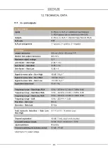
12.1. In- and outputs
In- and outputs
Inputs
3 x RCA, 2 x XLR, 2 x additional Input Modules
1 x RCA bypass (can be switched to IN4-XLR)
Outputs
2 x RCA, 2 x XLR, 1 x Monitor/Tape Record (RCA)
XLR ratio
0 dB
XLR pin assignment
1 = ground, 2 = positive, 3 = negative
Line stage
Output resistance
130 ohms RCA; 150 ohms XLR
Monitor Out output resistance
240 ohms
Maximum output voltage
12 V
Gain factor – Gain High
25 dB = 18.5
Gain factor – Gain Med
18 dB = 7.8
Gain factor – Gain Low
12 dB = 4
Signal-to-noise ratio – Gain High
-98 dB / 38 µV *
Signal-to-noise ratio – Gain Med
-104 dB / 18 µV *
Signal-to-noise ratio – Gain Low
-110 dB / 8 µV *
Equivalent noise level
14 nV √ Hz
Frequency range – Gain High, RCA
10 Hz – 200 kHz -0.7 dB / 0.7 MHz -6 dB
Frequency range – Gain Med, RCA
10 Hz – 200 kHz -0.3 dB / 1.3 MHz -6 dB
Frequency range – Gain Low, RCA
10 Hz – 200 kHz -0.2 dB / 2.1 MHz -6 dB
Frequency range – XLR
10 Hz – 200 kHz -1.5 dB
Rise time – Gain Low
350 ns
Slew rate – Gain Low
60 V/µs
Total harmonic distortion – Gain Low,
Med, High
0.01 % at 3 V / 10 kohms Load
Channel separation
-90 dB / 1 kHz, input short-circuited
Crosstalk between inputs
-80 dB / RCA, -95 dB XLR / 1 kHz
Input resistance
50 kohms
Channel matching via volume control
0.5 dB – 70 dB
* referring to 3 V output voltage

