28
10. OPTIONS
10.2.3. Assembling the phono input modules
The phono input modules are assembled in the same way as the line input modules, though their
assembly is simpler due to an absence of cables to be connected.
Note:
If your system is not equipped with a phono main circuit board (phono RIAA), you can
theoretically also insert the phono inputs, but no sound can be produced!
The RIAA board is
the basis and prerequisite for listening with phono
.
Module assembly
! WARNING !
Electric shock: Parts carrying dangerous voltages may be exposed when opening the cover.
Before opening the cover, switch off the device and unplug the power cord.
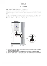
1. Loosen the M4 screws on the cover and pull off the cover plate upwards.
2. Loosen the 4 Phillips-head screws on the corresponding rear cover panel and remove the cover
panel.
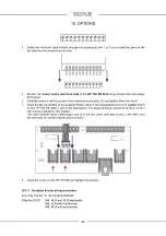
3. Loosen the screws on the corresponding terminal screw strip
.
4. Insert the module into the slot so to insert the module pins into the screw-connector on the main
circuit board.
5. Then, screw the rear panel back on.
6. Re-tighten the screws on the terminal screw strip. Do not tighten them too much!
7. Screw the cover back on.
10.2.4. Available phono input modules
See inlay manual “In- and Output Modules”
Effective 11/23: IN1: MM RCA
IN2: MC RCA
IN3: MC XLR
IN6: MC RCA Step-Up-Transformer switchable
IN7: MC XLR Step-Up-Transformer switchable


