25
10. OPTIONS
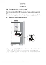
4. Guide the line-level input module through the opening at slot 1 or 2 so to insert the pins on the
pin strip into the terminal screw strip.
5. Secure the module
to the rear front side
of the
HP 700 SE
first
using screws from the empty
front panel.
6. Carefully screw in all the screws to the terminal screw strip. Do not tighten them too much.
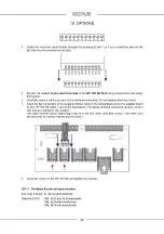
7. Insert the flat connectors of the supplied ribbon cable in the designated slot on the adapter board
on the HP 700 SE (slots 1 and 2 are equivalent). The blade terminal cannot be twisted, since it
can only be inserted in one position.
The input module ribbon cable plugs only fit in the two outer slots with 4 pins. (The other slots
are reserved for connecting the phono board.)
8. Close the cover on the HP 700 SE
and tighten the screws.
10.1.2. Available line-level input modules
See inlay manual “In- and Output Modules”
Effective 07/23:
IN4: RCA and XLR switchable
IN8: XLR with transformer
IN9: RCA with transformer


