CS9350
INSTALLATION MANUAL
3
AP-40800 - 1.0
CAUTION
Make sure to unpack this product with three
persons or more.
NOTE
Make sure to hold the specified positions when lifting
the product.
This prevents the product from being fallen and
broken.
Do not hold the media guide. This may affect the
accuracy and correct operation of the product.
No.
Name
1
Grips
2
Rubber grips
No.
Name
3
Rubber leg tips
4
Media guide
3
2
4
1
3
1
4
2
2
4
4
3
1
1
1
4
1
Front
4
2
3
2
1
3
2
1
1
2
2
1
2
3
4
5
1
2
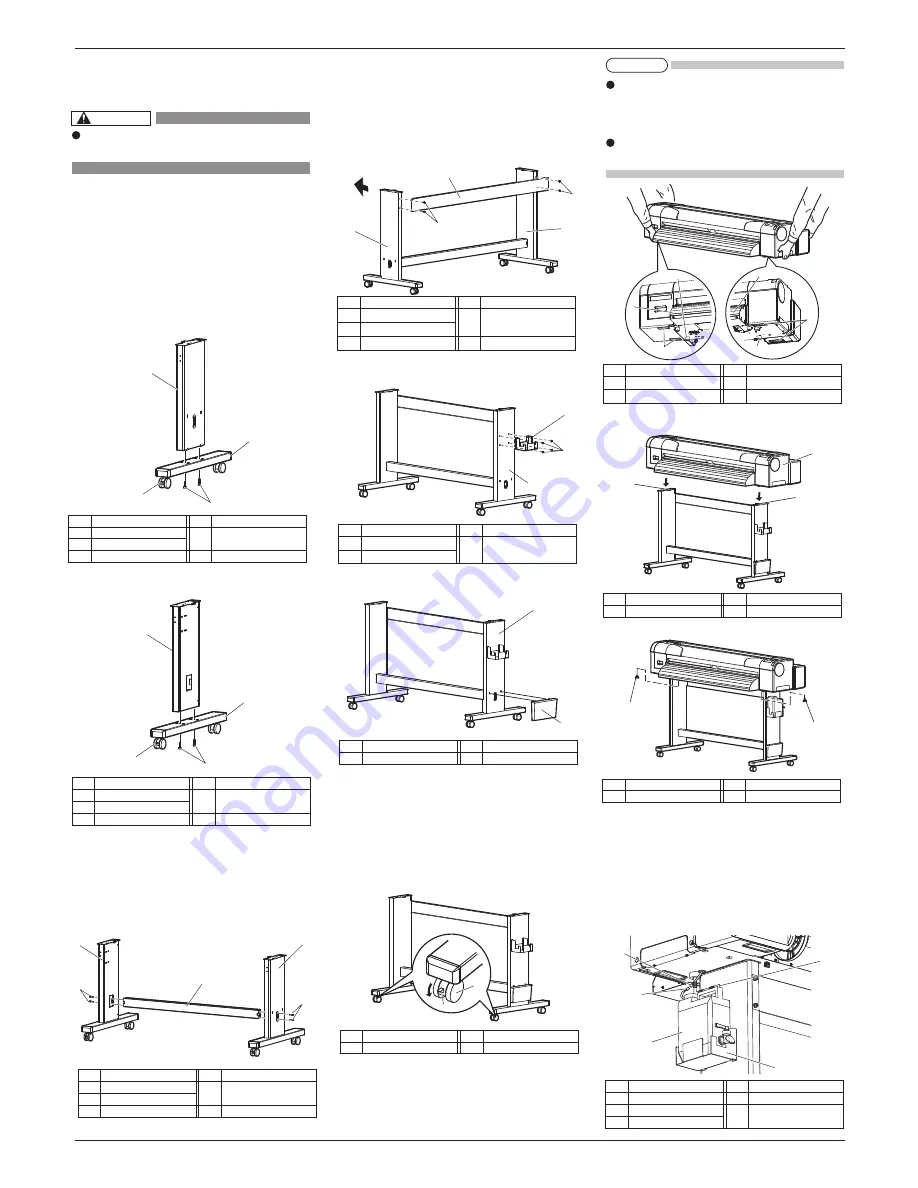
3 Assembling
Procedures for assembling this product are explained.
3.1 The stand assembling procedure
If you will use the stand, assemble it in accordance
with the following steps.
1. Follow the steps shown below to assemble the
right side of the stand.
a. Attach the right support to the caster section.
b. Fasten two hexagon socket head cap screws
with the enclosed hexagonal wrench.
2. Assemble the left side of the stand in a similar
way to step 1.
3. Follow the steps shown below to attach the central
beam to the legs (left, right).
a. Attach the central beam and four hexagon socket
head cap screws to the stand (the left, the right).
b. Fasten the hexagon socket head cap screws with
the enclosed hexagonal wrench, and fasten the
central beam.
4. Follow the steps shown below to attach the
Stabilizer to the Stand.
a. Use 4 Hexagon socket head cap screws to
attach the Stabilizer to the right and left sides
of the Stand (2 each side).
b. Tighten the Hexagon socket head cap screws
using the Hexagonal wrench.
5. Attach the waste fluid tank holder to the right
stand using four screws.
6. Attach the book holder to the right side of the stand.
7. Confirm that each component is fastened firmly
by gently shaking the stand.
3.2 Assembling the stand
Attach the stand to the printer in accordance with the
following steps.
1. Lock two casters on the front side.
2. Hold the following positions when lifting the product.
Panel side
: two grips under the product
Opposed side :two rubber grips under the product
3. Place the product on the stand so that the rear rubber
leg tips fit into the holes on the stand.
。
4. Attach two butterfly bolts to the stand.
5. Follow the steps shown below to set the Waste
fluid tank.
a. Put the Waste fluid tank in the Waste fluid
tank holder.
b. Attach the Waste fluid tube to the Waste fluid
tank.
c. Attach the Waste fluid sensor cable to the
Waste fluid sensor connector.
No.
Name
4 Hexagon socket head cap
screws
No.
Name
1
Right support
2
Caster lock
3
Caster section
No.
Name
4 Hexagon socket head cap
screws
No.
Name
1
Left support
2
Caster lock
3
Caster section
No.
Name
4 Hexagon socket head cap
screws
No.
Name
1
Central beam
2
Leg (left)
3
Leg (right)
No.
Name
1
Leg (right)
No.
Name
2
Book holder
No.
Name
1
Casters
No.
Name
2
Caster locks
No.
Name
1
Printer main body
No.
Name
2
Holes on the stand
No.
Name
1
Butterfly bolts
No.
Name
4 Waste fluid sensor cable
5
Waste fluid sensor
connector
No.
Name
1
Waste fluid tank holder
2
Waste fluid tank
3
Waste fluid tube
No.
Name
1
Stabilizer
2
Stand (left)
3
Stand (right)
No.
Name
4 Hexagon socket head cap
screws
No.
Name
1
Stand (right)
2 Waste fluid tank holder
No.
Name
3 Waste fluid tank holder
stabilizing screws
No.
Name
1
Stand (right)
2 Waste fluid tank holder
No.
Name
3 Waste fluid tank holder
stabilizing screws
No.
Name
1
Stand (right)
2 Waste fluid tank holder
No.
Name
3 Waste fluid tank holder
stabilizing screws
3
4
1
3
4
2


