background image

AcquiSuite Ally 12 & 48 User Guide (Rev D)


29 | 

P a g e


I

NSTALLATION 

S

EQUENCE 


The following section illustrates the  model.  The  components are slightly different, but follow the same 
procedure. 
  

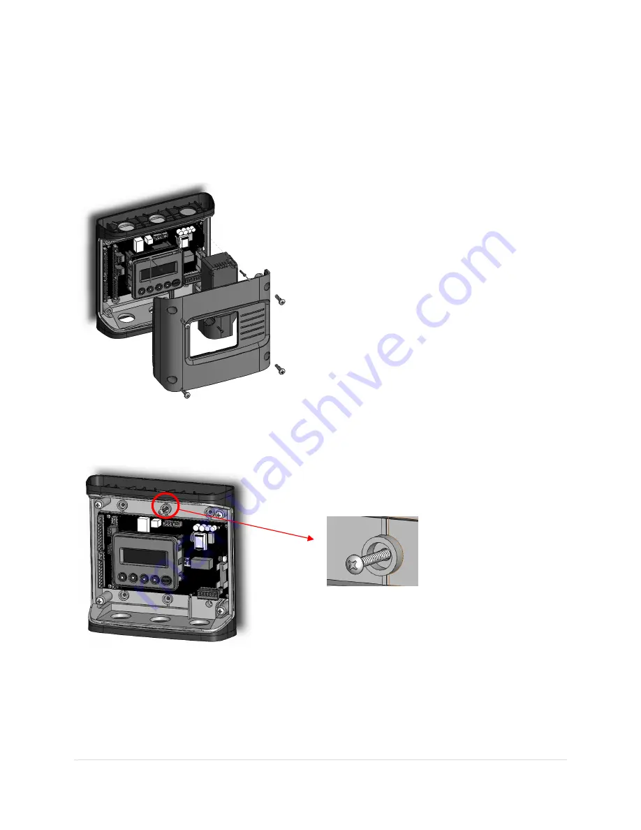
STEP 1)

 Remove top cover screws (4x) and high voltage cover screws (2x) 

 provided 


STEP 2)

 Locate, mark, and drill wall mounting points (2x

6x

customer supplied) 

The plastic enclosure itself can be used as a template for marking the drill locations on the wall. 


If the meter is not available for use as a drill template, a drawing indicating the spacing between mounting 
holes can be found in the appendix. The centerline holes are intended for fastening to wall studs. If hollow 
wall fasteners are used, the outer 4 mounting points are recommended. 


#8 Fastener 


Содержание AcquiSuite Ally

Страница 1: ...Revision C 11 18 User s Guide AcquiSuite Ally 12 48 Advanced Multi Circuit Meter And AcquiSuite Ally Configuration Console Software ...

Страница 2: ...Ally Power Meters 2018 Obvius Inc All rights reserved This manual may not be reproduced or distributed without written permission from Obvius AcquiSuite is a trademark of Obvius Inc Windows Windows 7 Windows 8 and Windows 10 are registered trademarks of Microsoft Corporation ...

Страница 3: ...mming and Scripting Overview 15 Meter Configuration Details 16 Install the Software 16 CONNECTION CONFIGURATION OPTIONS USING OBVIUS ALLY CONFIGURATION CONSOLE 16 Recommended Connection via USB AB Cable 16 Ethernet Network Connection 17 DYNAMIC HOST CONFIGURATION PROTOCOL DHCP 17 DIRECT 18 NETWORK SCAN 19 LAUNCH CONFIGURATOR 19 Obvius Ally Configuration Console Software Overview 20 Obvius Ally Con...

Страница 4: ...nication Verification 37 Obvius Ally Configuration Console Web Application 37 Physical Interface Verification 38 Serial Setup Verification 38 LAN Ethernet Network Verification 38 DHCP 38 STATIC IP 38 Protocol Verification 39 Modbus Settings 39 Modbus RTU Settings 39 Modbus TCP Settings 39 BACnet Settings 39 BACnet MSTP 39 BACnet IP 39 Pulse Inputs 40 ALARM SPDT 41 12 Volt Auxiliary Power 41 Access...

Страница 5: ...9 Register Organization 49 Element vs System Scope 49 Configuring Element and Channel Register for Service Types 50 Configuring System Registers 51 Modbus Protocol Commands 52 BACnet 53 BACnet Structured View 53 Appendix A ACQUISUITE Ally LCD Menu Navigation 55 MENU NAVIGATION 56 COMMUNICATION NAVIGATION 57 Appendix B Enclosure Dimensions 58 Appendix C Mounting Templates 59 Appendix D ACQUISUITE A...

Страница 6: ...cols that operate over an RS 485 serial network and BACnet IP and Modbus TCP are supported over Ethernet A USB port is also provided as the preferred connection for on site configuration and can be run concurrently with an RTU Unpacking the Unit The AcquiSuite Ally can be ordered with optional product features which are identifiable on the part number label AcquiSuite Ally Part Numbering Scheme AM...

Страница 7: ... All user connections are made on the circuit board Connectors are identified by function and include polarity markers Element ID Element ID LCD Display Navigation Buttons Plate Ground Serial Model MAC ID s Voltage Input 1 Voltage Input 2 AMC48 mounting plate version shown ...

Страница 8: ...AcquiSuite Ally 12 48 User Guide Rev D 8 P a g e AMC12 enclosure version with display shown cover removed ...

Страница 9: ...ved protection when operating the device CAUTION THIS METER MAY CONTAIN LIFE THREATENING VOLTAGES QUALIFIED PERSONNEL MUST DISCONNECT ALL HIGH VOLTAGE WIRING BEFORE SERVICING THE METER WITH THE HIGH VOLTAGE TOUCH SAFE COVER REMOVED Symbols on Equipment Denotes caution See manual for a description of the meanings DENOTES HIGH VOLTAGE RISK OF ELECTRICAL SHOCK LIFE THREATENING VOLTAGES MAY BE PRESENT...

Страница 10: ...be used on the AcquiSuite Ally 12 Ally 48 meter No accessories are approved for use with the AcquiSuite Ally 12 Ally 48 meter other than those specified in the Obvius product literature and price sheets If the meter appears damaged or defective first disconnect all power to the meter Then call or email technical support for assistance Obvius 20497 SW Teton Avenue Tualatin OR 97062 503 601 2099 866...

Страница 11: ...connection to Class 2 equipment Secure current transformer and route conductors so that they do not directly contact live terminals or bus CTs shall be listed to UL2808 Meter Installation Safety Requirements AcquiSuite Ally meters must be installed in accordance with local electrical codes Use copper conductors only Connection to the mains terminals shall be made with 14 AWG minimum wire gauge Ext...

Страница 12: ...ing section gives an overview of these activities followed by details in the next section CONFIGURATION DATA VIEWING OPTIONS The AcquiSuite Ally meter has multiple methods for configuration and data viewing The most powerful interface is provided with a PC Laptop or Tablet running Windows and is encouraged for complex installations The Ally Configuration Console software is required for configurin...

Страница 13: ... Values All Meter Parameters Waveform Capture Harmonic Analysis All Element View Phasor Plot Alarms All Meter Parameters Single Element View Voltage Current VA VAR kWh Single Element View All Meter Parameters Configuration Entire Meter Visual Guides Copy Paste Entire Meter except alarms Text Based Communications Only Entire Meter Register Based Security PINs Enforced Factory Support Level 3 Read O...

Страница 14: ...s of project Installation of Obvius Ally Configuration Console Software Connect USB Ethernet cable from PC to meter Establish communication with meter Firmware update if desired Configure software for anticipated meter setup Field wiring documentation Set Alarms Set Security PINs Meter Installation Overview Performed by licensed electrician Tools Typical Work Mounting hardware customer supplied Wi...

Страница 15: ...TU device Add wire terminations if required Confirm meter communication settings Meter health metrics check for setup errors Analytics Obvius Ally Configuration Console Correct instrumentation Set Alarms Set security PINs Checklist RTU Programming and Scripting Overview Tools Typical Work Laptop PC Remote Access to RTU Remote troubleshooting Register List Confirm meter communication settings Confi...

Страница 16: ...ified web browser interface The web browser can be accessed from the USB port to support Mac users Install the Software Insert the Obvius Ally Configuration Console thumb drive into the computer or download from the Obvius FTP site qualified Obvius personnel only The installer should start automatically If it does not browse the thumb drive and locate the AllyConfigurationConsoleInstaller exe prog...

Страница 17: ...equence is using USB to configure a meter for Ethernet communications at a static IP address and then switching from USB over to Ethernet to locate it This is facilitated in Obvius Ally Configuration Console by pressing the Refresh Connectivity icon located in the upper right hand corner ETHERNET NETWORK CONNECTION Configuring the Ally meter over Ethernet requires that the meter be powered from an...

Страница 18: ...cation settings or the PC network configuration LCD Display For units equipped with an LCD display navigate to Communications Ethernet Settings DHCP OFF Change the IP address in the meter to match the subnet of your PC s IP address making the meter IP unique or note the current address on the meter and prepare to configure your PC s IP settings as shown below Once the PC and Ally meter are set to ...

Страница 19: ... that includes the system description register IP address serial number and communication configuration Highlight the desired meter and select OK Test or Setup Note that the effectiveness of this technique is highly dependent on the configuration of the PC running Obvius Ally Configuration Console which may have more than one network card and the network configuration Rescans can be used to make m...

Страница 20: ...us are accessed under the central drop down list which has a content filter for viewing basic metering data or extended data that can be helpful in troubleshooting The information displayed in the drop down list for each filter setting is summarized below Display Data Monitor Power Energy Demand Monitor Power Energy Demand Power Factor Waveform Capture Harmonics Phasor Plot Meter Setup Communicati...

Страница 21: ... mouse example Frequency CT Type Current Transformer models are selected in the drop down list and are identified by a combination of CT image and amperage range The parameters for the selected CT are automatically populated This information can be edited for custom use Service Type Select a service type from the drop down list A selection populates the fields with pre configured service type info...

Страница 22: ...AcquiSuite Ally 12 48 User Guide Rev D 22 P a g e Configuring Electrical Components using Obvius Ally Configuration Console ...

Страница 23: ...NET RS 485 Ethernet Modbus OR BACnet Modbus OR BACnet Modbus BACnet Modbus BACnet Set Serial Settings Set Modbus Address Set Serial Settings Set Device ID Set Max Masters optional Set Max Info Frames optional DHCP OR STATIC Set Modbus Port optional Set Device ID DHCP Static IP Set Static Address Set Subnet Mask Set Gateway Mask Press SEND SETUP TO METER Set MS TP Address Set BACnet Port optional ...

Страница 24: ...a consistent set of conditions The text entry fields in grey are configuration aids and are NOT retained by the meter Only the fields with a black background are stored in the meters memory or in configuration files NOMINAL VALUES Entering alarm thresholds based on percent of nominal values is helpful when alarm conditions are desired to be centered around electrical components or industry standar...

Страница 25: ...ck icon launches the Window Calendar and allows the user to any desired date and time Set Time to Now populates the current time Press the OK button to commit this time to the RTC chip onboard the meter Real Time Clock Power Source The RTC integrated circuit is a stand alone low power circuit within the AcquiSuite Ally meter Time is kept in the absence of a connected external power source AC or US...

Страница 26: ...figuration Console in the Advanced menu Click the Download button By default the name of the data file will include the Serial Number of the Meter and the System Description followed by Datalog see below After pressing OK the entire data path will be displayed The data log is a Comma Separated Values CSV file that can be opened in Excel or another program The data will be listed in Chronological O...

Страница 27: ... b Use a network discovery tool to find the address by connecting and disconnecting the Ethernet cable c Set the meter to a static address using the serial interface 2 Connect your smart device to the same subnet as the AcquiSuite Ally meter 3 Open a Web Browser 4 Enter the AcquiSuite Ally Ethernet address into the web browser AUTHENTICATION Because the AcquiSuite Ally Web App can be viewed and co...

Страница 28: ... and to the AcquiSuite Ally meter Meter Mounting Configurations Obvius AcquiSuite Ally 12 Ally 48 meters are sold in both embedded and fully enclosed form factors Enclosures are designed to be wall mounted and connected to electrical conduit Embedded versions are ready to be mounted inside a customer supplied NEMA enclosure and offer IP20 protection Care should be taken not to flex the circuit boa...

Страница 29: ...EP 2 Locate mark and drill wall mounting points 2x 6x customer supplied The plastic enclosure itself can be used as a template for marking the drill locations on the wall If the meter is not available for use as a drill template a drawing indicating the spacing between mounting holes can be found in the appendix The centerline holes are intended for fastening to wall studs If hollow wall fasteners...

Страница 30: ...AcquiSuite Ally 12 48 User Guide Rev D 30 P a g e STEP 3 Mount conduit fittings conduits and blanking plugs STEP 4 Connect voltage leads DO NOT ENERGIZE METER WITH VOLTAGE COVER REMOVED ...

Страница 31: ...G VOLTAGE Connect the voltage leads L1 L2 L3 and N as necessary to the meter through a dedicated disconnect or circuit breaker A voltage lead of 14 AWG THHN Minimum 600VAC rating or equivalent is required IMPORTANT Verify the circuit breaker is marked as the disconnect breaker for the meter IP30 TOUCH SAFE with internal cover installed ...

Страница 32: ...under Meter Setup EXAMPLE LOADS Single Phase L1 N or L2 N 110 VAC Lighting Appliance Living Zone Single Phase L1 L2 220 VAC Water Heater Clothes Dryer Equipment with no neutral wire Split Phase L1 L2 220 VAC Service Entrance Equipment with neutral wire 3 Wire 1 Phase used On MAINS L1 N L2 N RōCoils Shown Single Phase 110 VAC Plug Loads L1 N or L2 N Single Phase 220 VAC Plug Load L1 L2 Meter is pow...

Страница 33: ...ing a ground wire to this terminal If the neutral terminal is left open L L measurements will be accurate but L N measurements may not be symmetric If a ground wire is connected to the Neutral terminal 2mA will flow into the ground wire Connect the Neutral wire or Ground wire to V INPUT 1 N on the meter Meter Power Connect all phases to the V INPUT 1 terminal Label as Disconnect 3 Wire 3 ɸ DELTA l...

Страница 34: ...entation placement Arrow points toward load or as instructed by CT label Arrow points away from Panel or as instructed by CT label Placed on First Conductor of voltage Reference L1 L2 circuits are placed on L1 Observe wiring color and polarity Use the Shield wire if provided connect to PCB terminal marked S Wiring Guide for CT Types Split Hinged Solid Core CTs Rogowski Coil CTs White Positive Blac...

Страница 35: ...n and indicates how to connect CTs to the Ally meter for each service type For service types that are not specifically listed it is recommended to choose single phase service and configure each channel individually Three phase loads are illustrated on the left and split phase loads on the right as an example only Elements are fully interchangeable on the meter ...

Страница 36: ...difications are anticipated a computer interface is recommended Physical Connections on an RS 485 Multidrop Network The AcquiSuite Ally meter uses a 2 Wire Half Duplex RS 485 Implementation Termination Resistors are NOT included on the AcquiSuite Ally meter If the AcquiSuite Ally meter is at the end of a daisy chain then connect a 120 ohm leaded resistor between the and terminal at the connector B...

Страница 37: ...nking character in the physical LCD The ENTER button is used to select a property and up down buttons are used to select among the values supported by the meter Note that changes to the meter configuration are limited to the communication interface using the LCD If additional changes such as CT type are required they must be made using a software interface Example LCD Navigation OBVIUS ALLY CONFIG...

Страница 38: ...ssigned an address by a DHCP server as described below DHCP If the AcquiSuite Ally meter is configured for DHCP when the meter is powered on or the Ethernet cable is inserted the meter is assigned an IP address by the DHCP server This address appears on the meter LCD or can be found through connection with Obvius Ally Configuration Console or the AcquiSuite Ally Web App The IP address assigned to ...

Страница 39: ...ter needs to be set to match the address expected by the RTU and is normally part of the network specification The default address for element A is 1 MODBUS TCP SETTINGS Modbus Port The AcquiSuite Ally meter uses the industry standard Port 502 for Modbus This port number can be changed although this is considered an advanced setting and should be left at 502 unless this generates a conflict on the...

Страница 40: ... a dry contact Form A Relay or open collector outputs The AcquiSuite Ally pulse inputs are compatible with low speed meters The pulse duration must exceed 50mS in both the logic low and high state allowing for a maximum input frequency of 10 Hz Pulse scaling resetting and accumulated values are accessed through registers and are system in scope Refer to the register list Obvius Ally Configuration ...

Страница 41: ... through Modbus register BACnet object 2451 The Master Alarm relay can be hard wired to an interrupt or polling circuit in a host system allowing for a more rapid response than the data polling frequency if desired The status of each alarm is determined by reading status registers Refer to the register list or Configuration Console manual for more information Note The Master Alarm relay is intende...

Страница 42: ...f PIN protection that users can choose to assign for restricting access to meter information The PIN logic is described in the figure below The default user entry on power up or time out is 0000 which satisfies both the Read Only and the Read Write default register settings USING THE PERMISSION REGISTERS The AcquiSuite Ally meter uses both a Read Only register and a Read Write register to compare ...

Страница 43: ...r user who needs the ability to correct setup errors in the meter The default PINs 0000 allow new users to reset the Read Write PIN from either the AcquiSuite Ally Web App or Obvius Ally Configuration Console Permissions cannot be set through the LCD interface READING PINS OVER MODUS OR BACNET Obvius Ally Configuration Console can be used to directly report the Read Only and Read Write PINS under ...

Страница 44: ... The LCD display will list the elements having at least one channel with a low power factor CHECK ELEMENTS A EF Use the navigation buttons to highlight a specific element and hit enter or just hit enter and move from element to element using the keys Within each element identified on the top line of the display the status of each channel is identified as good PF 0 55 or bad PF 0 55 ELEMENT F CH1 G...

Страница 45: ...isplacement power factor of a load is below 0 55 an angle greater than 57 degrees between voltage and current the AcquiSuite Ally meter will flag it as a phasing error Obvius Ally Configuration Console has a PhasorPlot feature that can be used to study the voltage and current vectors of a given meter element Check for Low Power Factor Obvius Ally Configuration Console Real Time Values All power fa...

Страница 46: ...act on the amplitude of the Power Factor A moderate power factor 0 7 in concert with a negative power is a clue that the CT is on backwards but is on the correct phase Electrical Power Quadrants with Reversed CT shown Check that the wattage has the correct sign Designated for loads Obvius Ally Configuration Console Real Time Values Confirm Sign of Power For All Elements AcquiSuite Ally Web App Rea...

Страница 47: ...er reports overall harmonic content in power THD based on it s measurement of Power Var and Apparent Power as illustrated in the figure below This method cannot indicate the harmonic number or distribution but provides the overall harmonic content In many circumstances users are interested in the harmonic content of current In cases where the voltage is very sinusoidial the THD measurement is a go...

Страница 48: ...sters allow for transformer winding ratios or other scaling adjustments to be included in the meter processing to eliminate post process scaling Adjustments for voltage are global to the meter while CT s can be adjusted on a channel by channel basis The multiplier is a floating point number and can also be used for post installation calibration if desired Default values are 1 0 CT PHASE SHIFTS Cur...

Страница 49: ...these correspond to electric circuits Logically the term Element describes the scope of a data item register or point Modbus register or BACnet object Each Element based point is accessed by choosing the appropriate Modbus address BACnet object range or BACnet structured view Elements in turn have points that refer to individual channels or to SUMS or AVERAGES of those channels Registers that cont...

Страница 50: ...ign CH1 2220 2223 2224 2225 2224 2225 2221 2222 2226 CH2 2229 2232 2227 2228 2233 2234 2230 2231 2235 CH3 2238 2241 2236 2237 2242 2243 2239 2240 2244 Configurations 4 Wire 3 ɸ Wye Service Type 1 V_Input 1 or 2 Description 31 Char Channels Volt Ref CT Type Range Phase Shift CT Multiplier CT Sign CH1 L1 N 1 mV 1 or RōCoil 2 Any 0A 3 0 to 3 0 Any 0 1 0 or 1 CH2 L2 N 2 mV 1 or RōCoil 2 Any 0A 3 0 to ...

Страница 51: ...tion it is recommended that the CT settings reflect those from CH1 rather than being left at factory default to facilitate configuration validation from the RTU Disabled OFF Service Type 5 V_Input 1 or 2 Description 31 Char Channels Volt Ref CT Type Range Phase Shift CT Multiplier CT Sign CH1 L1 N 1 OFF 0 Any 0A 3 0 to 3 0 Any 0 1 0 or 1 CH2 L2 N 2 OFF 0 Any 0A 3 0 to 3 0 Any 0 1 0 or 1 CH3 L3 N 3...

Страница 52: ...gister in the string block must be written to sequentially without interruption either by using a write multiple command or by sending single register commands back to back The final character in the string MUST be a NUL character ASCII 0 The meter will process the entire string only if these two conditions are met otherwise the data is ignored This special processing has been implemented to prote...

Страница 53: ... Ethernet Ethernet versions can register as Foreign Devices to a BBMD BBMD stand for BACnet IP Broadcast Management Device The BBMD IP address can be set from the Ally Configurataion Console or through character string object 2264 A value of 0 0 0 0 disables foreign device registration This process requires a processor soft reset BACNET STRUCTURED VIEW The AcquiSuite Ally meter supports the Struct...

Страница 54: ...nalog Value AV Analog User Settings floating point numeric outputs Binary Value BV User Boolean Settings Multi State Value MSV Enumerated Settings BitString Value BSV Bitfield Status Words and Settings Positive Integer Value PIV Restricted Range User Settings Character String Value CSV User Text string settings The following online BACnet resources are also helpful http www bacnet org ...

Страница 55: ... LCD navigation map is shown in diagram form in the next few pages The About Meter menu is the most commonly accessed item which requires 5 down presses or 1 up rolling menu to access The About Meter menu contains the following items which are displayed 4 lines at a time and accessed by using the keys on the front display ...

Страница 56: ...AcquiSuite Ally 12 48 User Guide Rev D 56 P a g e MENU NAVIGATION ...

Страница 57: ...AcquiSuite Ally 12 48 User Guide Rev D 57 P a g e COMMUNICATION NAVIGATION ...

Страница 58: ...AcquiSuite Ally 12 48 User Guide Rev D 58 P a g e APPENDIX B ENCLOSURE DIMENSIONS Enclosure Dimensions ...

Страница 59: ...AcquiSuite Ally 12 48 User Guide Rev D 59 P a g e APPENDIX C MOUNTING TEMPLATES Enclosure Drill Template ...

Страница 60: ...AcquiSuite Ally 12 48 User Guide Rev D 60 P a g e AMC48 Mounting Plate Template AMC12 Mounting Plate Template ...

Страница 61: ... resetting fuse Waveform Sampling 1 8 kHz 3 6 HZ Parameter Update Rate 1 second Measurements Volts Amps kW kVAR kVA aPF dPF kW demand kVA demand Import Received kWh Export Delivered kWh Net kWh Import Received kVAh Export Delivered kVAh Net kVAh Import Received kVARh Export Delivered kVARh Net kVARh THD Theta Frequency All parameters for each phase and system total Accuracy 0 2 ANSI C12 20 2010 Cl...

Страница 62: ...ing System Windows 7 Windows 8 Windows 10 Communications Port RS 485 USB standard Ethernet available One USB Port required on PC Safety FCC Compliance This device has been tested and found to comply with the limits for a Class A digital device pursuant to part 15 of the FCC Rules These limits are designed to provide reasonable protection against harmful interference when the equipment is operated ...

Страница 63: ...63 P a g e 20497 SW Teton Avenue Tualatin OR 97062 503 601 2099 866 204 8134 USA Only 2018 Obvius All rights reserved Subject to change without notice ...

Отзывы: