


OBO Bettermann
48 | EN
Mounting on a support system
6 3
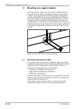
Mounting fittings
With all the fittings, the holes of the appropriate lock plate serve as a
template for the hole pattern of the threaded rods.
6 3 1
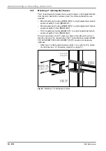
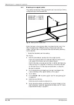
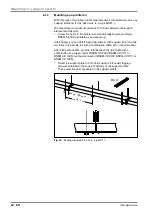
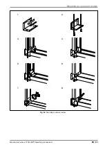
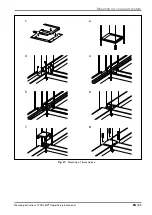
Mounting flat angles
Plan duct routing at a 90° angle and at the same height as the flat angle.
The lock plate suspended from threaded rods (BSKM-GF 0407, BSKM-
GF 0711 or BSKM-GF 1025) is used as a support element for the duct
sections. Together with the screwed-on flat angle (BSKM-FW 0407,
BSKM-FW 0711 or BSKM-FW 1025), it ensures the necessary tightness.
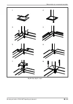
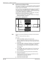
See Fig. 52:
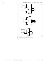
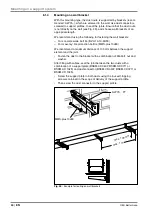
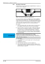
1
Stick the self-adhesive sealing strip to the lock plate.
2
Fasten the threaded rods to the ceiling and fasten the lock plate to
the threaded rods with washers and nuts at the desired height.
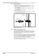
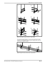
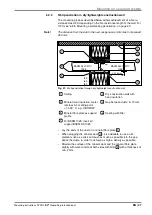
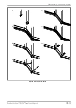
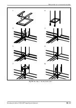
3
Shorten the ducts as necessary and then re-drill the duct fastening
holes (see Fig. 12 on page 18). If necessary, use locking brackets
for the duct lid (see “4.4 Inserting locking brackets” on page 19).
Remove the duct lid and fix the duct sections with two self-tapping
screws each (contained in the scope of delivery of the lock plate) on
the lock plate.
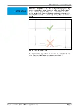
ATTENTION
Comply with the minimum bending radii of the cables!
Cables can be damaged on bending. When laying the cables in the flat
angle, ensure that the minimum bending radius, prescribed by the cable
manufacturer, is observed.
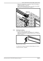
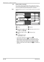
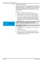
4
Insert cables.
5
For duct BSKM 1025: insert lid support (see “4.5 Using lid support”
on page 20).
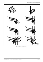
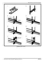
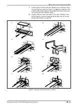
6
Attach the duct lid firmly.
7
Attach the flat angle and screw on with the supplied nuts.
8
Using connecting screws (contained in the scope of delivery of the
flat angle), create the equipotential bonding (see “8.1 Create equipo-
tential bonding” on page 72).


