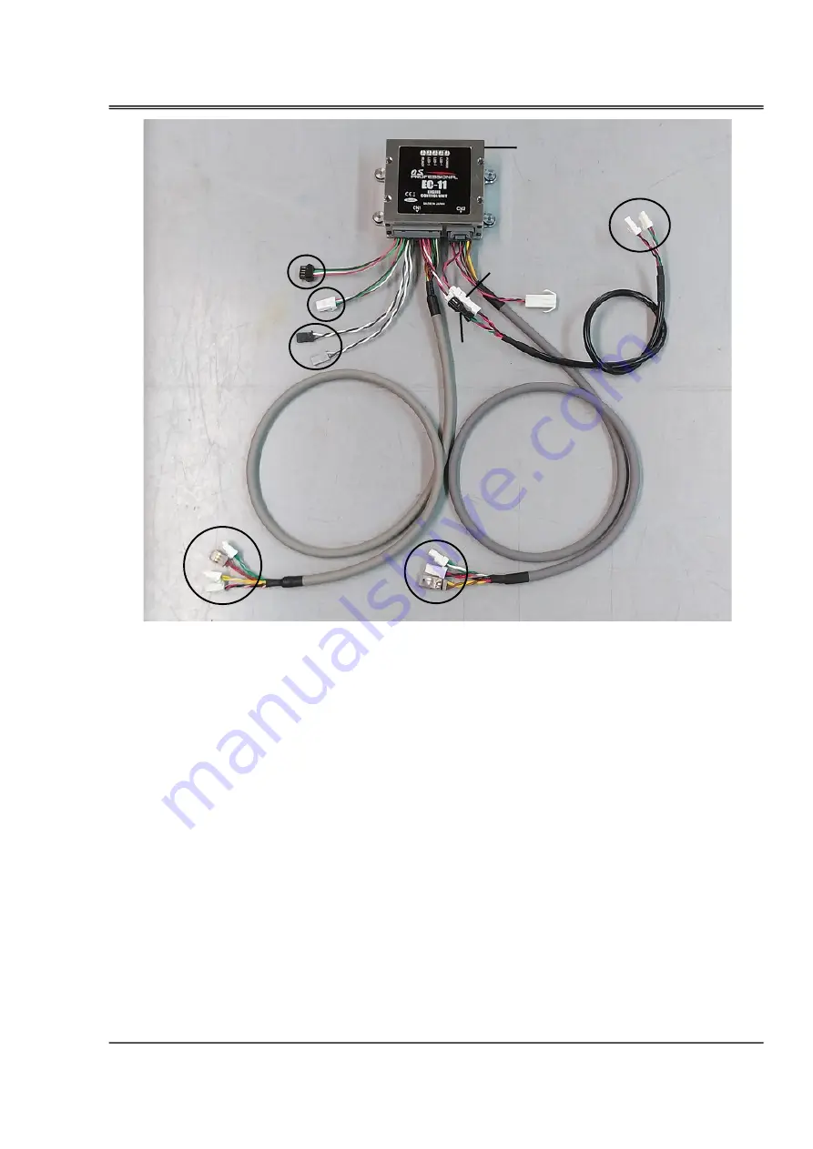
[A] Wiring harness A (Sensor and Communication section) {CN1}
A-1
・
Throttle signal input (PWM VIH=2.6V
,
VIL=0.4V
,
MAX5.5V)
・
Fuel trim signal input (PWM VIH=2.6V
,
VIL=0.4V
,
MAX5.5V)
A-2
・
Serial communication (UART
,
TTL logic level is 3.3V)
A-3
・
Fuel pressure sensor
A-4
・
Intake air temperature sensor
・
Cylinder head temperature sensor
・
Manifold air pressure sensor
・
Crankshaft rotation sensor
A-5
・
CAN communication
[B] wiring harness B (Drive section) {CN2}
B-1
・
Power supply (DC10V
~
17V, MAX 1.5A)
B-2
・
Fuel pump
B-3
・
Ignition signal
・
Throttle servo
・
Injector
[C] pump connection cord (extendable)
C-1
・
fuel pressure sensor
・
fuel pump unit
Engine control unit (ECU)
16
[B]
A-1
B-1
A-2
A-3
[A]
[C]
TO FUEL PUMP UNIT &
FUEL SENSOR UNIT
Connect to engine
B-2
B-3
Connect to engine
A-4
A-5
C-1
ECU
Содержание GF40U-FI
Страница 7: ...6 Accessories CAN communication code the connector for CAN communication...
Страница 31: ...PM 02 FUEL PUMP UNIT SP 01 FUEL PRESSURE SENSOR UNIT Engine parts list P1 30 S1 S4...
Страница 33: ...VALVE ADJUSTING TOOL KIT GF 32 Engine parts list F10...
Страница 34: ...Demantions 33 Unit mm Unit mm...
Страница 35: ...Demantions 34 Unit mm...
Страница 36: ...MEMO 35...


