


NXP Semiconductors
UM11009
PCA9745B demonstration board OM13524
UM11009
All information provided in this document is subject to legal disclaimers.
© NXP Semiconductors N.V. 2016. All rights reserved.
User manual
Rev. 1 — 23 June 2016
8 of 28
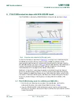
5. Hardware description
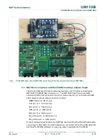
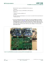
Fig 3
shows the following items on the hardware:
•
CON1 (9-pin male connector) is connected to SPI master device.
•
CON2 (9-pin female connector) is connected to next SPI daisy-chain device.
•
CON3 (5-pin male connector) is no use for PCA9745B SPI device.
•
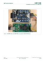
CON4 (14-pin male connector) is connected to J1 on WIN-I2CUSB hardware board
as I2C master device to drive this demo board (no connect for SPI signals)
•
J1 selects V
DD
power for PCA9745B, connected 1-2 for V
DD
= 5 V and connected 2-3
for V
DD
= 3.3 V.
•
J13 selects LED
power for all LEDs, connected 1-2 for V
LED
= 3.3 V and connected 2-
3 for V
LED
= 5 V.
•
J7 (7-8), J9 (9-10) and J10 (9-10) to select Vss for pin 2, SDO for pin 3 and /CS for
pin 4 respectively.
•
LED[0:15] 16-channel output to drive four White LEDs (WHT_LED[1:4]) and four
RGB LEDs (RGB_LED[1:4]).
•
TP2 and TP3 are GND pins for probing use.
•
TP1 can be connected as external reset signal to /RESET pin when J6 is open.
•
TP4 can be connected as external output enable signal to /OE pin for
blinking/dimming control when J11 is open.
•
All jumpers default setting and function as shown in
Table 1
.
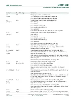
Table 1.
Jumper settings for test and evaluation
Jumper
Default setting
Comment
J1
(3-pin)
2-3
(V
DD
= +3.3V)
This jumper is used to select V
DD
for PCA9745B
1-2: 5V
2-3: 3.3V
J2
(3x2-pin)
1-2
(Rext=1 K,
57 mA@max)
This 3x2 jumper is used to select Rext (pin1) value for PCA9745B
1-2: select Rext = 1K and max. o/p current is 57.3 mA
3-4: select Rext = 1.5K and max. o/p current is 38.25 mA
5-6: select Rext = 2K and max. o/p current is 28.6 mA
J3
(2-pin)
Open
Short: external 1.1K pull-up resistor for SDI on PCA9745B
Open: no external pull-up resistor for SDI on PCA9745B
J4
(2-pin)
Open
Short: external 1.1K pull-up resistor for SCLK on PCA9745B
Open: no external pull-up resistor for SCLK on PCA9745B
J5
(2-pin)
Short
Short: connect VDD_IN to V
DD
(pin28) on PCA9745B
Open: connect current meter to measure the I
DD
on PCA9745B
J6
(2-pin)
Open
Short: force /RESET (pin25) to GND
Open: 10K pull-up /RESET (pin25) to V
DD
J7
(4x2-pin)
7-8
This 4x2 jumper is used to select input value for pin 2
Open: floating
1-2: select V
DD
3-4: select pull-up with 31.6K
5-6: select pull-down with 34.8K
7-8: select GND