


NXP Semiconductors
UM11009
PCA9745B demonstration board OM13524
UM11009
All information provided in this document is subject to legal disclaimers.
© NXP Semiconductors N.V. 2016. All rights reserved.
User manual
Rev. 1 — 23 June 2016
4 of 28
4. Installation
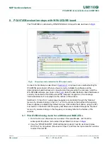
4.1 Fm+ development board and WIN-SPIUSB software
The OM13524 is a daughter card to the OM13260 Fm+ I2C bus development board with
SPI driver which is part of the Fm+ development board kit (OM13320). You may
download the software, user manual, and find ordering information at the NXP web site:
http://www.nxp.com/demoboard/OM13320.html#documentation
The Win-SPIUSB software from The Boardshop runs on Windows 98SE, ME, 2000, and
XP and is compatible with any PC hardware having a minimum of a Pentium processor
and an USB port. The software allows the user to select one of the SPI-bus driver from a
menu and also provides a Universal mode (SPI Expert mode) to allow users to create
their own SPI-bus commands with the same SPI-bus devices.
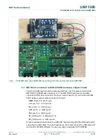
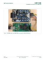
4.2 OM13524 connection to Fm+ I2C bus development board
The OM13260 Fm+ I2C bus development board should be disconnected from your PC
before connecting the OM13524 PCA9745B demo board on to it. The OM13524 board
has a 9-pin male connector (CON1) that connects to the 8-pin male connector (CN16) on
the Fm+ I2C bus development board using six jumper wires as shown in the
Fig 1
.
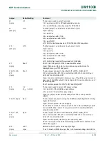
CON1
(9-pin)
CN16
(8-pin)
3.3V (pin 4)
+3V3 (pin 2)
SCL (pin 5)
MCU_SCLK (pin 4)
GND (pin 6)
GND (pin 7)
SDA (pin 7)
MCU_MOSI (pin 3)
SPI_SDO (pin 8)
MCU_MISO (pin 1)
SPI_CSN (pin 9)
MCU_SSN (pin 6)