


NXP Semiconductors
UM11009
PCA9745B demonstration board OM13524
UM11009
All information provided in this document is subject to legal disclaimers.
© NXP Semiconductors N.V. 2016. All rights reserved.
User manual
Rev. 1 — 23 June 2016
17 of 28
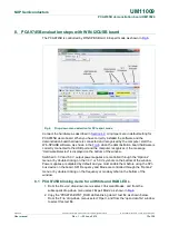
9. PCA9745B evaluation steps with Fm+ development board
The PCA9745B is controlled by Fm+ development board GUI in Expert mode as shown
in
Fig 8
.
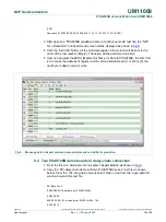
Fig 8.
Selecting Expert Mode from Fm+ development board GUI
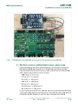
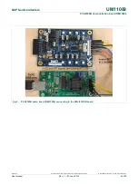
Connect the hardware as described in
Section 4.2
. All jumpers are in default setting for
PCA9745B demo board. When you have correctly installed the software and the
demonstration board hardware is connected and recognized by the computer, start the
Fm+ development board software. As shown in
Fig 8
, when the demonstration board
hardware is correctly connected to the USB port and the computer recognizes it, the
message “USB-I2C Hardware Detected” is displayed on the bottom of the window. SPI
Frequency is controlled through the “Options” menu or by clicking on the frequency
symbol on the bottom of the window.
9.1 PCA9745B gradation demo for White and Red LEDs
1. From the ‘Device’ drop-down menus select ‘Expert Modes’ as shown in
Fig 8
.
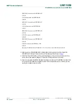
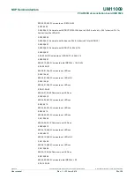
2. Copy the “PCA9745B gradation demo in continuous mode“ text file as shown below.
From the ‘File’ drop-down menus select ‘Open’, and from the “open data file” window
to select this text file.
SPI Data File 2
0,04,05,Comments: LEDOUT0 turn on WHT_RED LEDs
,02,00