


NXP Semiconductors
UM11009
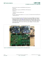
PCA9745B demonstration board OM13524
UM11009
All information provided in this document is subject to legal disclaimers.
© NXP Semiconductors N.V. 2016. All rights reserved.
User manual
Rev. 1 — 23 June 2016
10 of 28
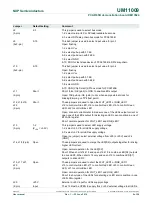
Jumper
Default setting
Comment
J24
(2-pin)
GND
External GND input for LEDs supply voltage
J25, J27 J29,
J31
(2-pin)
Short
These jumpers are used to open the WHT_LED4 or RGB_LED4
J25 to control white LED, J27 to control Red LED, J29 to control Green
LED, J31 to control Blue LED
Open: connect current meter to measure one of the LEDs output current or
open one of the LEDs output for detecting an LED open condition in one of
EFLAGn register
Short: normal operation for WHT_LED4 and RGB_LED4
J26, J28 J30,
J32
(2-pin)
Open
These jumpers are used to short the WHT_LED4 or RGB_LED4
J26 to control white LED, J28 to control Red LED, J32 to control Green
LED, J30 to control Blue LED
Open: normal operation for WHT_LED4 and RGB_LED4
Short: to short one of the LEDs for detecting an LED short condition in one
of EFLAGn register
CON1
9-pin male connector
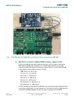
This 9-pin male connector is connected to SPI master device or next daisy-
chain device
CON2
9-pin female connector
This 9-pin female connector is connected to next SPI daisy-chain device
CON3
5-pin male connector
No use for PCA9745B SPI device
CON4
14-pin
header
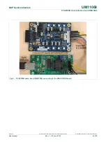
This 14-pin header is used to connect to Win-I2CUSB hardware board as
I2C master device to drive this demo board (no use for PCA9745B)
TP1
Test Point 1
This TP1 is used to drive /RESET input pin25 from external when J6 is
OPEN
TP2, TP3
Test Point 2/3
These two test points are GND for probe ground connection
TP4
Test Point 4
This TP4 is used to drive /OE input pin5 from external when J11 is OPEN