


NXP Semiconductors
UM11762
NTS0304EUK-ARD evaluation board
Tables
Arduino connectors pin chart and usage ...........8
VCC_LDOOUT1 voltages ............................... 13
VCC_LDOOUT2 voltages ............................... 14
LDO enable status .......................................... 14
NTS0304EUK-ARD jumpers ........................... 14
NTS0304EUK-ARD test points ........................15
Abbreviations ...................................................25
Figures
The NTS0304EUK-ARD board picture, top
view (up) and bottom view (down) .................... 6
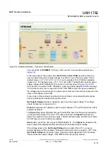
NTS0304EUK-ARD block diagram ....................7
NTS0304EUK-ARD – Arduino connectors ........ 9
NTS0304EUK-ARD – Level translator .............10
NTS0304EUK-ARD – Digital potentiometer .... 11
NTS0304EUK-ARD – SPI / I2C-bus
external connector ...........................................12
NTS0304EUK-ARD – LDO section ................. 13
NTS0304EUK-ARD Jumper locations ............. 15
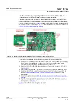
NTS0304EUK-ARD daughterboard and
IMXRT1050 EVK board, before starting .......... 17
daughterboard / IMXRT1050 EVK board
operation ..........................................................18
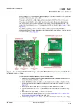
NTS0304EUK-ARD daughterboard and
LPCXpresso55S69 mother board, before
starting .............................................................19
NTS0304EUK-ARD daughterboard /
LPCXpresso55S69 motherboard operation .....20
interposer board, and i.MX 8M Mini
LPDDR4 EVK, before starting .........................21
NTS0304EUK-ARD daughterboard / i.MX
8M Mini LPDDR4 EVK board operation .......... 22
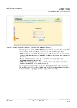
Graphical interface at start-up
(“SETTINGS” tab activated by default) ............23
Graphical interface – “Dynamic” tab
activated .......................................................... 24
Graphical interface – “Static” tab activated ......25
UM11762
All information provided in this document is subject to legal disclaimers.
© NXP B.V. 2022. All rights reserved.
User manual
Rev. 1.0 — 27 May 2022
28 / 29