


UM11082
All information provided in this document is subject to legal disclaimers.
© NXP B.V. 2018. All rights reserved.
User Manual
Rev. 1.1 — 12 January 2018
16 of 18
NXP Semiconductors
LPC8N04 Development Board
User Manual
7.2 LED
Array
An array of 35 LEDs, arrange as 5 columns by 7 rows, is provided on the reverse side of
the DP section of the board. Connections are shown in
Table 3
and
Table 4
. The row
signals connect to the anode of all 5 LEDs in that row, and the cathodes of each LED are
connected to the column signals. To turn on an LED, the row signal should be driven high
and the column signal driven low. The LEDs are low current devices, with a nominal
current draw of around 5mA, but the LED array is intended to be used with a row scanning
technique, so only one row is driven at a time. If all LEDs are driven continuously this may
lead to damage to the LPC8N04 device. An example of driving the LEDs with a scanning
technique is provided in the app_demo example code mentioned in
Section 3.3
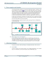
7.3 Speaker and Speaker Driver
A surface mount speaker (LS1) is provided on the reverse side of the DP section of the
Board. The speaker is driven by a driver built from discrete transistors in a Class B
topology, with PIO0_3 used to provide the input signal. P9 must be set to connect PIO0_3
to the driver circuit (see
Figure 3
). An 820 resistor to ground is connected at the amplifier
input in order to avoid excessive current draw when the amplifier is not being used (i.e.
when PIO0_3 is not driven or is disconnected at P3.)
Note that the amplifier current draw is relatively high, so it is not recommended to use the
speaker with Coin cell B, and energy harvesting will not support speaker operation.
Table 3.
LED array row connections
LED row
LPC8N04 pin
Shared with
0
PIO0_2
1
PIO0_7
2
PIO0_8
3
PIO0_9
4
PIO0_1
5
PIO0_0
6
PIO0_3
Speaker (selected using P9)
Table 4.
LED array column connections
LED column LPC8N04 pin
Shared with
0
PIO0_6
1
PIO0_5
2
PIO0_4
3
PIO0_10
SWCLK (selected using P8)
4
PIO0_11
SWDIO (selected using P7)