


NXP Semiconductors
UM11587
KITVR5510xA0EVM Evaluation Kit User Guideline
Figures
LEDs, switches, and the PMIC ......................... 7
Connectors ........................................................ 8
Jumpers .............................................................9
Test points .......................................................11
KITVR5510xA0EVM layout – top .................... 12
KITVR5510xA0EVM layout – layer 2 .............. 12
KITVR5510xA0EVM layout – layer 3 .............. 13
VR551-xA0EVM layout – layer 4 .....................13
KITVR5510xA0EVM layout – layer 5 .............. 14
KITVR5510xA0EVM layout – layer 6 .............. 14
KITVR5510xA0EVM layout – layer 7 .............. 15
KITVR5510xA0EVM layout – bottom .............. 15
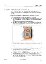
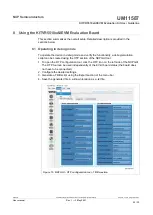
Freedom board ................................................19
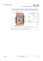
Connecting to a reference board with K82F
only ..................................................................22
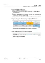
NXP GUI - OTP configuration tool - TBB
creation ............................................................23
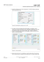
Reading FS_STATES [0x18] register from
safety section (0x21h) .....................................24
Selecting test-mode option ..............................24
M_TM_STATUS1 (0x25) ................................. 25
FS_STATES (0x18) ......................................... 25
Selecting the config source as “script” ............ 26
Fuse box status ...............................................26
UM11587
All information provided in this document is subject to legal disclaimers.
© NXP B.V. 2021. All rights reserved.
User manual
Rev. 1 — 3 May 2021
31 / 32