


NXP Semiconductors
UM11587
KITVR5510xA0EVM Evaluation Kit User Guideline
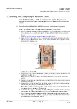
4.3.1 LEDs, switches, and the PMIC
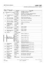
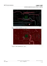
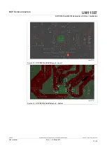
shows the location of the LEDs, switches, and the PMIC on the
KITVR5510xA0EVM board. The meaning of each of the LEDs is shown in
Figure 1. LEDs, switches, and the PMIC
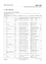
Label Color
Name
Indication
D4
Green
PGOOD_G
External PGOOD signal – PGOOD released
D6
Green
RSTB_G
External RSTB signal – RSTB released
D12
Red
RSTB_R
External RSTB signal – RSTB asserted low
D13
Red
PGOOD_R
External PGOOD signal – PGOOD asserted low
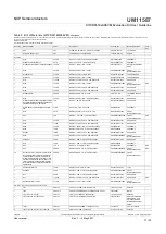
D14
Red
INTB
External INTB signal
D15
Red
FSOB_R
External FSOB signal – FSOB asserted low
D18
Green
VPRE
VPRE_OUT enabled
D20
Green
VBST
BOOST_OUT enabled
D21
Green
VBAT
VBAT on
D29
Green
FSOB_G
External FSOB signal – FSOB released
Table 1. LEDs
UM11587
All information provided in this document is subject to legal disclaimers.
© NXP B.V. 2021. All rights reserved.
User manual
Rev. 1 — 3 May 2021
7 / 32