


NXP Semiconductors
UM11587
KITVR5510xA0EVM Evaluation Kit User Guideline
4 Getting to Know the Hardware
This section describes the kit features and provides information on the board and its
components.
4.1 KITVR5510xAEVM overview
The KITVR5510xA0EVM is a development platform built around the VR5510 PMIC as
the Device Under Test (DUT). The board allows designers to evaluate various functions
of the DUT. Connectors on the board provide the capability of measuring power-related
functions such as power, efficiency, loop stability, load transients, etc. Jumpers on the
board enable the selection of various capabilities, such as I/O control and switching
regulator feedback. The EVM also allows the VR5510 to be set into Debug Mode to
facilitate the debugging of faults generated by the device.
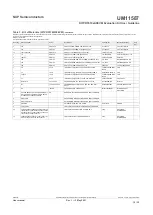
The KITVR5510xA0EVM includes NXPs FRDM-K82F development platform board.
The FRDM-K82F attaches to the bottom of the board and serves as the communication
interface between the KITVR5510xA0EVM and GUI software on the PC.
4.2 KITVR5510xA0EVM features
The KITVR5510xA0EVM evaluation board offers the following features:
•
VR5510 debug mode support
•
Connectors for measuring:
–
Loop stability
–
Load transients (BUCK12 or VPRE)
–
AMUX/JTAG
–
Signal and power
–
Efficiency
•
Load terminals for VPRE, BUCKs, BOOST, LDOs, and HVLDO regulator output
•
Jumper selection for:
–
I/O control (RSTB, PGOOD, STANDBY, PWRON2, PSYNC, VDDIO)
–
Debug mode entry/exit
–
Switching regulators (BUCKx, VPRE) feedback
•
Multiple test points
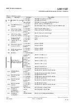
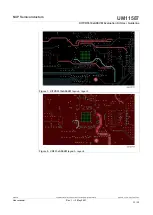
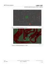
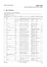
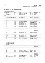
4.3 Board descriptions
The KITVR5510xA0EVM board provides connectors, jumpers, and test points for all of
the evaluation functions supported by the kit.
UM11587
All information provided in this document is subject to legal disclaimers.
© NXP B.V. 2021. All rights reserved.
User manual
Rev. 1 — 3 May 2021
6 / 32