7
22. 04. 21. Document Number 671506
Nuaire | Western Industrial Estate | Caerphilly | CF83 1NA | nuaire.co.uk
BESPOKE BOXER
Installation Manual
3.9 Control Dampers
Care should be taken to ensure that all spring return actuators have
stopped running and completed their stroke. If not, the connection
needs to be loosened and the actuator should be left to drive until the
motor stops running.
When the unit is powered, dampers should be checked to ensure that
they operate freely and close tightly.
3.10 Final Inspection
•
Thoroughly inspect the unit after installation is complete.
•
The inside of the unit should be checked; any objects which may
have been left should be cleared.
•
Check fan impellers, scrolls and outlets.
•
Remove any transit protection fittings that may be attached to the
fan or motor base frame, and that all traps are primed.
•
Close all access door seals for damage, and replace any panels that
have been removed.
4.0 ELECTRICAL INSTALLATION
The electrical wiring must be carried out by competent persons, in
accordance with good industry practice and should conform to all
governing and statutory bodies i.e. IEE, CIBSE etc.
Ensure suitable earth bonding is maintained on all AHU sections.
4.1 Wiring (If Applicable)
4.1.1 AC Motor Fans
Inverter speed control is required for these units and can be provided by
Nuaire as optional extras, any inverters should be configured to match
the design and running frequency that is provided on the datasheet of
each specific fan.
Care should be taken to ensure that the rotation of three phase motors
correspond with the direction shown on the frame.
All electrical connections to the fan are to be made using flexible cable
and containment materials to allow for the movement of anti-vibration
mounts.
12
Typical Fan (AC Motor) Wiring
L1 L2 L3
U1
W1
PE
V1
U2
W2
V2
3 Phase only
Inverter Speed Control
Motor
Terminal
Connections
Inverter Drive
INPUT
OUTPUT
Notes:
Inverters are typically unconfigured, and require configuring
to suit project specific fans and control applictions.
Internal Factory Connection
Mandatory Customer Connection
Key:
U1
W1
V1
400V 3 phase 50Hz supply
Motor
3 Phase
U1
W1
V1
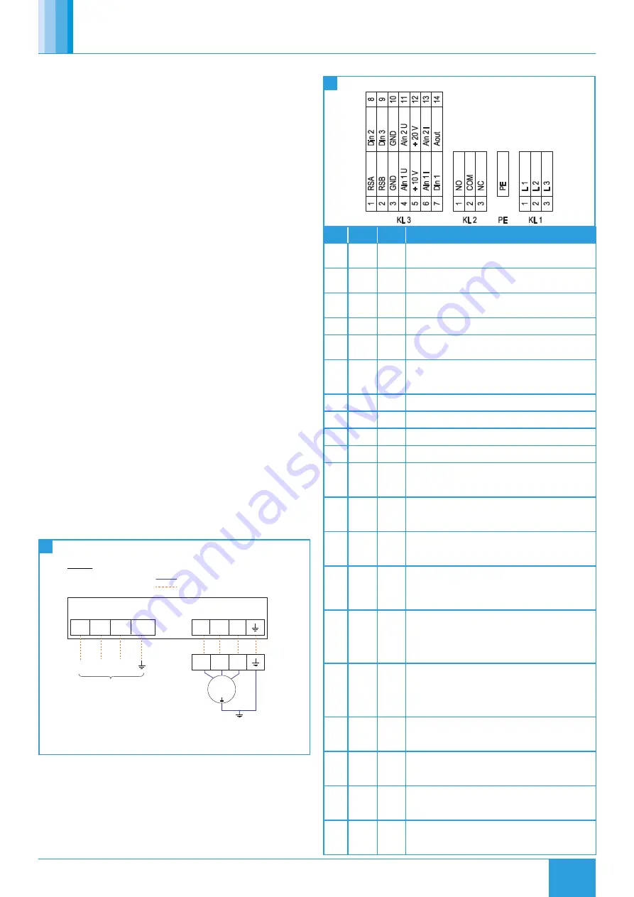
4.1.2 EC Motor Fans
13
Typical Fan (EC Motor) Wiring
No.
Conn.
Desig.
Function / Assignment
KL1
1
L1
Mains supply connection, supply voltage 3~380-480 VAC;
50/60 Hz
KL1
2
L2
Mains supply connection, supply voltage 3~380-480 VAC;
50/60 Hz
KL1
3
L3
Mains supply connection, supply voltage 3~380-480 VAC;
50/60 Hz
PE
PE
Earth connection, PE connection
KL2
1
NO
Status relay, floating status contact; normally open; close
with error
KL2
2
COM
Status relay; floating status contact; changeover contact;
common connection; contact rating 250 VAC / max. 2 A
(AC1) / min. 10 mA
KL2
3
NC
Status relay, floating status contact; break with error
KL3
1
RSA
Bus connection RS-485, RSA, MODBUS RTU; SELV
KL3
2
RSB
Bus connection RS-485, RSA, MODBUS RTU; SELV
KL3
3/10
GND
Signal ground for control interface; SELV
KL3
4
Ain1 U
Analogue input 1, set value: 0-10 V, Ri = 100 kΩ,
parametrisable curve, only usable as alternative to input
Ain1; SELV
KL3
5
+ 10 V
Fixed voltage output 10 VDC, +10 V ±3%, max. 10 mA,
short-circuit-proof, power supply for external devices (e.g.
potentiometer), SELV
KL3
6
Ain1 I
Analogue input 1, set value: 4-20 mA; Ri = 100 Ω,
parametrisable curve, only usable as alternative to input Ain1
U; SELV
KL3
7
Din1
Digital input 1: enabling of electronics, Enabling: open pin
or applied voltage 5-50 VDC. Disabling: bridge to GND or
applied voltage <1 VDC. Reset function: triggers software
reset after a level change to <1 VDC; SELV
KL3
8
Din2
Digital input 2: parameter set switch 1/2, according to
EEPROM setting, the valid/used parameter set can be
selected via bus or via digital input DIN2. Parameter set
1: open pin or applied voltage 5-50 VDC. Parameter set 2:
bridge to GND or applied voltage <1 VDC; SELV
KL3
9
Din3
Digital input 3: controller function of integrated controller,
according to EEPROM setting, the controller function of the
integrated controller is normally/inversely selectable per bus
or per digital input. Normal: open pin or applied voltage 5-50
VDC. Inverse: bridge to GND or applied voltage <1 VDC; SELV
KL3
11
Ain2 U Analogue input 2, actual value: 0-10 V, Ri = 100 kΩ,
parametrisable curve, only usable as alternative to input
Ain2; SELV
KL3
12
+ 20 V
Fixed voltage output 20 VDC, +20 V +25/-10%, max. 50 mA,
short-circuit-proof, power supply for external devices (e.g.
sensors); SELV
KL3
13
Ain2 I
Analogue input 2, actual value: 4-20 mA, Ri = 100 Ω,
parametrisable curve, only usable as alternative to input Ain2
U; SELV
KL3
14
Aout
Analogue output 0-10 VDC, max. 5 mA, output of the current
motor level control coefficient / motor speed parametrisable
curve; SELV


