NTI UNIMUX SERIES USB KVM SWITCH
20
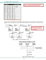
DDC
The UNIMUX is designed to transfer DDC information from the monitor to the CPU so that the CPU is able to update EDID data
about the monitor it connects to.
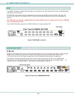
DDC information is downloaded from the attached monitor and stored in the UNIMUX when the UNIMUX is first power-ON
(monitor must be ON first), or by pressing the “DDC” button after the UNIMUX is powered-ON (used when hot-plugging the
monitor).
Note: Make sure your monitor is in digital DVI mode (not analog DVI) for video to be viewed and for the proper EDID table
to be communicated to the CPU.
Once the DDC information is recorded, the UNIMUX will transfer it to each connected CPU.
Figure 15-DDC Button Location
AUDIO SUPPORT
(Optional)
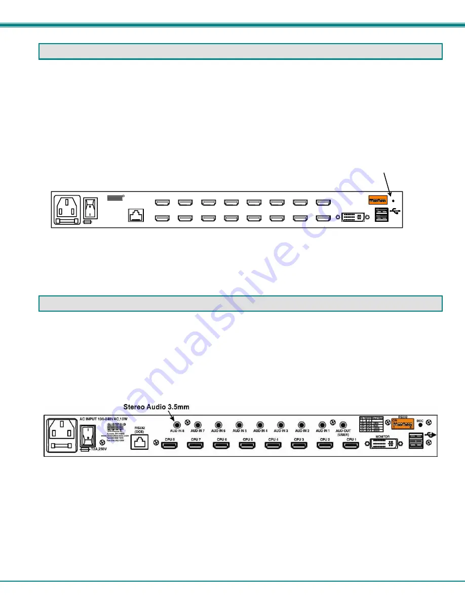
Models with audio support include 3.5mm stereo jacks for connection to audio sources and an output device. Audio from either
the same sources as the video, keyboard, and mouse or from separate sources (any standard line level audio source
(1.23Vrms/3.47Vp-p max.)) will be heard through devices such as self-powered stereo speakers or headphones.
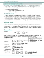
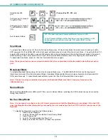
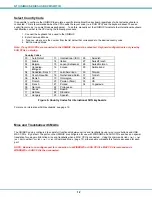
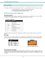
Audio signals are switched along with the keyboard, mouse and video signals using the buttons on the UNIMUX switch.
Connections to “AUD IN” ports will switch at the same time as like-numbered “CPU” ports when controlling the switch. For
example, if “CPU 1” is switched to “CPU 2”, then “AUD IN 1” will also switch to “AUD IN 2”.
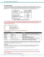
Figure 16- Rear View of UNIMUX-DVIA-8HD
Rear View of UNIMUX-DVI-16HD
CPU 1
CPU 2
CPU 3
CPU 4
CPU 5
CPU 6
CPU 7
CPU 8
CPU 9
CPU 10
CPU 11
CPU 12
CPU 13
CPU 14
CPU 15
CPU 16
RS232
250V,2A
MONITOR
NTI
Tel:330-562-7070
Fax:330-562-1999
1275 Danner Dr
Aurora, OH 44202
www.networktechinc.com
R
DDC
1
8
ON
RS232
DDC Button

