background image

11

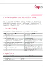
6  Electromagnetic Field and Personal Safety

During the heating function, the IHN010 unit generates a maximum magnetic flux density of less than 5�7µT at a distance 
of half a meter away� The device is therefore within the range that applies to the household sector for induction cooktops� 
Modern pacemakers are protected from such interference� Nevertheless, the manufacturers recommend that those using 
pacemakers remain a minimum distance of 40cm from the induction heater� People with cardiac pacemakers should check 
with their doctor about possible disrupting effects�

7  Troubleshooting

Display

Fault

Action

E01 E

General system failure

Return heater for repair

E02 E

Memory failure

Return heater for repair

E03 E

Overheated coil

Wait until the inductive coil cools

E04 E

No workpiece in place

Place workpiece on device

E05 E

Temperature increase of less than 1°C (2°F) every  
15 seconds (or 1°C (2°F) every 30 seconds) 

Check the temperature probe connection� If the connection 
is OK, select the 30 second interval as described in section 
5 or operate the heater in TIME MODE�

E06 E

Temperature probe not connected (or defective)

Check the temperature probe

E07 E

Failure during current measurement

Return heater for repair

E08 E

Failure during communication with power printed  
circuit board

Return heater for repair

E09 E

Overheated printed circuit board

Wait until the printed circuit board cools� Alternatively, 
the PCB temperature will be displayed� The device can be 
re-started at a temperature below 40°C (displayed as <40)�

E10 E

Grid undervoltage detected

Connect the device to another socket or  
shorten the extension cord�

8  Spare Parts

Description

Part Number

Spare temperature probe

IHNP2SENSOR

Spare protective gloves

IHNGLOVES

Spare portable soft case for IHN010

IHN025-B

A system fault will be indicated by an acoustic signal and one of the following fault codes on the main display:

Содержание IHN010

Страница 1: ...USER MANUAL INDUCTION HEATER IHN010 SUBSCRIBE TO NSK NEWSLETTER SUBSCRIBE TO NSK NEWSLETTER ...

Страница 2: ...omponents 4 2 2 Technical Data 5 3 Preparation for Use 6 4 Operation 6 4 1 Function of Displays 7 4 2 Function of Buttons 7 4 3 Temp Mode 7 4 4 Time Mode 8 4 5 Temperature Measurement 9 4 6 Change of Temperature Unit 9 4 7 Demagnetisation 9 4 8 Power Level Selection 9 5 Safety Features 10 6 Electromagnetic Field and Personal Safety 10 7 Troubleshooting 11 8 Spare Parts 11 ...

Страница 3: ...ce Avoid contact with hot workpieces Wear the supplied protective gloves when handling hot workpieces Please ensure that you always use a power and temperature level that is appropriate for the workpiece in question to ensure that it is heated carefully and not damaged The device is intended for heating rolling bearings The manufacturer accepts no liability in the event of inappropriate or incorre...

Страница 4: ...ield induces a voltage targeted on the inner ring of the workpiece This creates eddy currents which efficiently heat the workpiece As the heat in the workpiece is generated by the current flow all other parts of the induction heater remain cold The heating process is based on the prin ciple of eddy currents so the workpieces to be heated should be composed of ferritic magnetic metals In case of do...

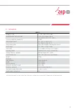
Страница 5: ...teps of 0 1 minutes Operating modes Automatic temperature or time mode Demagnetisation automatic Residual magnetism 2A cm Overall dimensions 340 x 250 x 64mm over cone 121mm Weight 3 5kg Workpiece Inner diameter Width External diameter 20mm and above Up to 60mm Up to 160mm Workpiece maximum weight Up to 10kg Workpiece materials Ferritic metals magnetic Maximum heating temperature 180 C 356 F Autho...

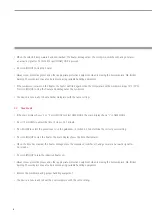
Страница 6: ...ug is correct Use the holding magnets in the measuring head of the temperature probe as a quick and easy way of checking whether the workpiece is made of ferritic metal magnetic and therefore can be heated optimally using the IHN010 induction heater The magnetic measuring head of the temperature probe is placed on the inner ring of the rolling bearing or the innermost point of the ring The tempera...

Страница 7: ... F If a different temperature is desired press UP or DOWN to adjust the temperature in steps of 1 C 2 F It may be desirable to heat bearings to temperatures above 110 C 230 F for increased mounting time To determine the maximum permitted temperature consult the specifications of the bearing manufacturer Always ensure the bearing does not lock due to an excessive expansion of the inner ring compare...

Страница 8: ...ngs 4 4 Time Mode If the main display shows C or F press MODE to select TIME MODE The main display shows t in TIME MODE Press UP or DOWN to adjust the time in steps of 0 1 minute Press POWER to select the power level Use the guidelines in section 4 8 to determine the correct power setting Press START STOP to start the heater The main display shows the time that remains When the time has elapsed th...

Страница 9: ...010 it is important that bearings with small internal clearance or slight preload are heated slowly Slow heating ensures that the bearing expands slowly thereby preventing damage to the bearing In addition it is possible that the ferrite cage and seals could be heated more quickly than the inner ring due to their low mass The shape weight size and internal clearances all affect the amount of time ...

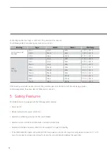
Страница 10: ...DE and DOWN at the same time Bearing Cage Shield Power Max Temp Deep groove ball bearings Steel Steel 20 110 C 230 F Steel Plastic 20 100 C 212 F Steel None 100 110 C 230 F Other bearings Steel Steel 20 110 C 230 F Brass Steel 20 110 C 230 F Plastic Steel 20 110 C 230 F Steel Plastic 20 100 C 212 F Brass Plastic 20 100 C 212 F Plastic Plastic 20 100 C 212 F Steel None 100 110 C 230 F Brass None 10...

Страница 11: ...increase of less than 1 C 2 F every 15 seconds or 1 C 2 F every 30 seconds Check the temperature probe connection If the connection is OK select the 30 second interval as described in section 5 or operate the heater in TIME MODE E06 E Temperature probe not connected or defective Check the temperature probe E07 E Failure during current measurement Return heater for repair E08 E Failure during commu...

Страница 12: ...uartier de l Europe 2 rue Georges Guynemer 78283 Guyancourt Cedex Tel 33 0 1 30573939 Fax 33 0 1 30570001 info fr nsk com Germany Austria Switzerland Nordic NSK Deutschland GmbH Harkortstraße 15 40880 Ratingen Tel 49 0 2102 4810 Fax 49 0 2102 4812290 info de nsk com Italy NSK Italia S p A Via Garibaldi 215 20024 Garbagnate Milanese MI Tel 39 02 995 191 Fax 39 02 990 25 778 info it nsk com Poland C...

Отзывы: