Page 12 of 32
© Brüel & Kjær Vibro
● C104958.002 / V04
Technical alterations reserved!
EN
4
Installation
Read the safety information in the chapter "Safety" before installation. To assemble the displacement
sensor system, proceed in the following order:
•
4.1 Assembling the displacement sensor
•
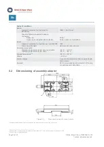
4.2 Assembling the driver (oscillator/demodulator)
•
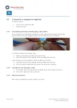
4.3 Connect the components together
•
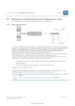
4.4 Setting up the measuring chain and the displacement sensor
•
Requirements:
•
The displacement sensor system is complete (se
e “Table 3-1) Components included in scope
•
The overall length of the measuring system neither exceeds nor falls below the nominal length.
•
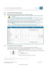
The required clearances and the width of the measuring track are considered
(8.3.2 Properties of the measuring track und 8.3.3 Required clearances and minimum
distances for displacement sensors)
•
Required clearances and minimum distances for displacement sensors.
•
The sensitivity of the target material is known.
Recommended accessories for trouble-free operation:
•
Install the driver in a housing/control cabinet. For this purpose, the protective driver housings
AC-2126 for up to 3 drivers and AC-2127 for up to 6 drivers are recommended.
•
Use shielded signal wiring (preferably AC-1112) between the driver and connected electronics.
The connection cable has to be heat-resistant at least + 85 °C.
•
Install the sensor cable between machine housing and driver housing in a protective steel
conduit.
•
Install the sensor cable between machine housing and driver housing in a protective steel
conduit.


