


N960 Controller
NOVUS AUTOMATION
4/6
Ai
ky
A2ky
A
larm
HY
steresis
ALARM HYSTERESIS 1 AND 2
: Defines the
difference between the measured value when the
alarm is activated and the value that is deactivated.
A1bl
A2bl
Al
arm
Bl
ocking
Initial Alarm block:
Yes
Enables initial block
No
Does not enable initial block
Pr.ty
Pr
ogram
Ty
pe
Type of program to be adopted by controller:
none
Does not adopt any type of program
rate
Adopts ramp to level function
Prog
Adopts complete Ramp and Level
program.
CALIBRATION LEVEL
All types of input and output are calibrated at the factory. If recalibration
is required, it must be performed by a specialist. If this cycle is
accessed accidentally, pass through all parameters without making
changes to their values.
pass
Password
. Input of the Access Password.
This parameter is presented before the protected
cycles. See item
Protection of Configuration
.
inL(
Input Low Calibration
. Enter the value
corresponding to the low scale signal applied to the
analog input.
ink(
Input High Calibration
.
Enter the value
corresponding to the full scale signal applied to the
analog input.
0vL(
Output Low Calibration
. Enter of the value
measured at the analog output.
0vk(
Output High Calibration
. Enter of the value
measured at the analog output.
rstr
Restore
. Restores the factory calibration for all input,
analog output and remote SP, disregarding
modifications carried out by the user.
(j
Cold Junction
. Adjusts the of cold junction
temperature value.
Pas.(
Password
. Allows defining a new access password,
always different from zero.
Prot
Protection
. Sets up the Level of Protection. See
Table 2
.
TYPE OF ADOPTED PROGRAM
Two forms of program execution are available in the controller. The
Program Type (
Pr.Ty
) parameter allows user to choose between
Ramp to Level
(
rate
) and a complete Ramp and Level program
(
Prog
). User can also choose to not execute any type of program
(
none
).
PROGRAMS OF RAMP AND SOAK
Available when the
Rate
option in the
Pr.Ty
parameter is selected.
The controller allows the process temperature to vary gradually from an
initial value until a specified final value, determining a Ramp-like behavior.
The initial value of the Ramp will always be the process initial
temperature (PV). The final value will always be the value defined in SP.
User determines the increase (or decrease) speed of the ramp in the
“
rAtE
” parameter, which defines a temperature variation rate in
degrees
per minute
. In order to disable the Ramp function, program the value
0.0
.
When the SP value is reached, the controller starts to control the
process in SP (level) by an interval of time or indefinitely.
The
t
SP
parameter, adjustable between 0 and 9999 minutes,
determines the level duration. At the end of the level, the control is
disabled (
run
=
no
) and
all
outputs are turned off. With value
0
in
t
SP
the control continues indefinitely without time limit.
As alarm can be associated at the end of the level. The
End.t
Alarm
Function determines that an alarm is activated at the end of the level.
Valid only with
t
sp
≠ 0.
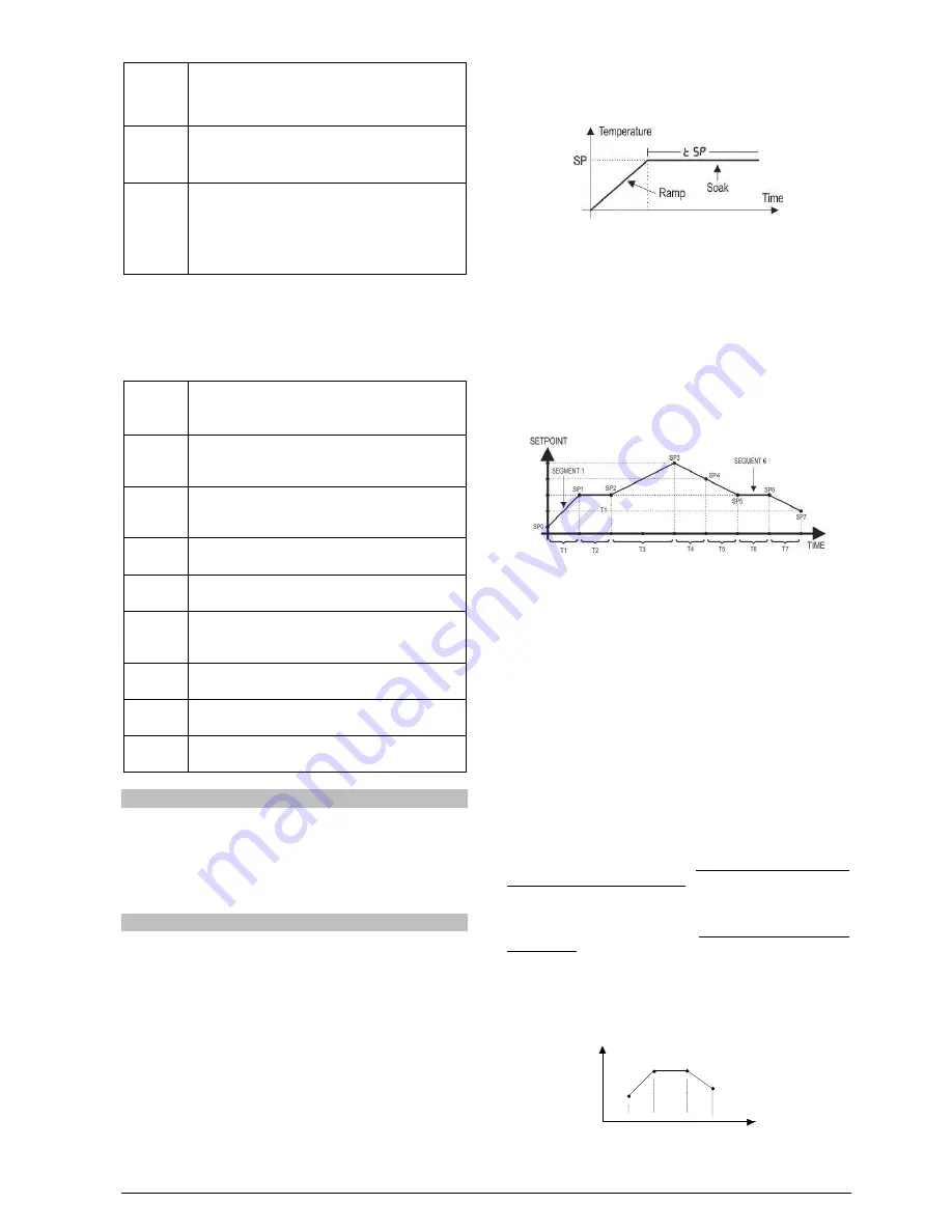
Fig. 2
- Level Ramp Function
Upon returning from a power failure, the controller automatically restarts
the execution of the Ramp to Level function. If the PV value is smaller
than the SP value, the Ramp restarts at this point until it reaches SP. If
the temperature is equal to SP, Level execution is restarted.
COMPLETE LEVEL AND RAMP PROGRAM
Available when the
Prog
option is selected in the
Pr.Ty
parameter.
The controller allows to elaborate one temperature ramp and level
program. This program is created from the SP value definition and time
intervals, defining up to nine (9)
program segments
. The figure below
shows a program model with 9 segments:
Fig. 03
- Example of a ramp and level program
The program created is permanently stored in the controller’s memory.
It can be modified freely, executed when necessary and repeated as
often as necessary.
In order to execute a program:
1- Turn off outputs (
rvn
=
NO
);
2- Enable execution of parameter
E.Pr
=
yes
;
3- Trigger start turning on outputs: (
rvn
=
yes
).
Once a program is initiated, the controller starts to automatically
generate the SP values defined for each program segment. SP
adjustment in the indication screen remains blocked.
PROGRAM TOLERANCE FUNCTION -
PTOL
The “
PtoL
” program tolerance program defines the maximum error
limit between the PV and SP values during program execution. If this
limit is exceeded, the timing of the segment (Pt1…Pt9) is interrupted
until the error is within the established tolerance. With a value > 0, the
user indicates in the program that priority must be given to PV
regarding the determined time values.
If zero tolerance (
Ptol
=
0
) is programmed, the controller executes
the program defined without considering eventual errors between PV
and SP. Thus, the user defines that the priority be given to the program
execution time.
PROGRAMS WITH FEW SEGMENTS
In order to execute a program with a smaller number of segments, just
program 0 (zero) for the time interval that follows the last segment of
the desired program.
SP
TIME
T1
T2
T3
PSP0
PSP1
PSP2
PSP3
T4=0
Fig. 04
- Example of a program with only 3 segments