N1040 Controller
NOVUS AUTOMATION
3/7
OPERATION
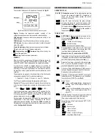
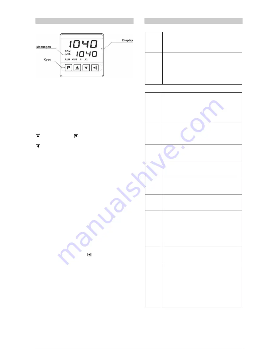
The controller’s front panel, with its parts, can be seen in the Fig. 02:
Fig. 02 - Identification of the parts referring to the front panel
Display: Displays the measured variable, symbols of the
configuration parameters and their respective values/conditions.
COM Indicator: Flashes to indicate communication activity in the
RS485 interface.
TUNE Indicator: Stays ON while the controller is in tuning process.
OUT Indicator: For relay or pulse control output; it reflects the actual
state of the output.
A1 and A2 Indicators: Signalize the occurrence of alarm situation.
P Key: Used to walk through the menu parameters.
Increment key and
Decrement key: Allow altering the
values of the parameters.
Back key: Used to retrocede parameters.
STARTUP
When the controller is powered up, it displays its firmware version for
3 seconds, after which the controller starts normal operation. The
value of PV and SP is then displayed and the outputs are enabled.
In order for the controller to operate properly in a process, its
parameters need to be configured first, such that it can perform
accordingly to the system requirements. The user must be aware of
the importance of each parameter and for each one determine a valid
condition.
The parameters are grouped in levels according to their functionality
and operation easiness. The 5 levels of parameters are:
1 – Operation / 2 – Tuning / 3 – Alarms / 4 – Input / 5 – Calibration
The “P” key is used for accessing the parameters within a level.
Keeping the “P” key pressed, at every 2 seconds the controller jumps
to the next level of parameters, showing the first parameter of each
level:
PV >>
atvn
>>
fva1
>>
type
>>
pass
>> PV …
To enter a particular level, simply release the “P” key when the first
parameter in that level is displayed. To walk through the parameters
in a level, press the “P” key with short strokes. To go back to the
previous parameter in a cycle, press
:
Each parameter is displayed with its prompt in the upper display and
value/condition in the lower display. Depending on the level of
parameter protection adopted, the parameter PASS precedes the
first parameter in the level where the protection becomes active. See
section Configuration Protection.
DESCRIPTION OF THE PARAMETERS
OPERATION CYCLE
PV + SP
PV Indication screen. On the higher display (red) the
value of the measured variable (PV) temperature is
shown. On the lower display (green), the control
setpoint (SP) is shown.
Sp.a1
Sp.a2
Alarm SP. Value that defines the alarm activation
point. For the alarms set up with the functions of the
type Differential, these parameters define deviations.
For the alarm function
ierr
, this parameter is not used.
Parameters shown in this level only when enabled in
the parameters
sp1.E
and
sp2.E
.
TUNING CYCLE
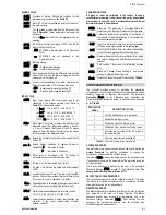
Atvn
AUTO-TUNE. Enables the auto-tuning function for the
PID parameters (
pb
,
ir
,
dt
). Defines the control
strategy to be taken:
off
- Turned off (no PID tuning);
Fast
- Automatic tuning;
Full
- More accurate automatic tuning.
PB
Proportional Band. Value of the term P of the control
mode PID, in percentage of the maximum span of the
input type. Adjust of between 0 and 500.0 %.
When set to zero (0), control action is ON/OFF.
ir
Integral Rate. Value of the term I of the PID algorithm,
in repetitions per minute (Reset). Adjustable between 0
and 24.00. Displayed only if proportional band
≠
0.
dt
Derivative Time. Value of the term D of the control mode
PID, in seconds. Adjustable between 0 and 250.0
seconds. Displayed only if proportional band
≠
0.
(t
Cycle time. Pulse Width Modulation (PWM) period in
seconds. Adjustable between 0.5 and 100.0 seconds.
Displayed only if proportional band
≠
0.
kyst
Hysteresis. Is the hysteresis for ON/OFF control (set in
temperature units). This parameter is only used when
the controller is in ON/OFF mode (Pb=0).
A(t
Action Control:
re
Control with Reverse Action. Appropriate for
heating. Turns control output on when PV is
below SP.
dir
Control with Direct Action. Appropriate for
cooling. Turns control output on when PV is
above SP.
sfst
SoftStart Function. Time interval, in seconds, while the
controller limits the control output (MV) rising rate
.
(Zero value disables the Soft Start function).
0vt1
0vt2
0vt3
0vt4
Assign functions to the Output channels OUT1, OUT2,
OUT3 and OUT4:
Off
- Not used;
(trl
- Control output;
A1
- Alarm 1 output;
A2
- Alarm 2 output;
A1a2
- Alarm 1 + Alarm2 (OR logic);
Lbd
- Loop Break Detect Alarm.

