background image


Do not adjust the lifting force on the gate so 
that  the  barriers  rise  without  any  assistance 
from the person operating the gate. 

CAUTION 

LIFTING FORCE ADJUSTMENT 

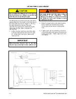
The lifting force required to open the gate can be 
adjusted based on the location of the wire rope in 
the clevis plate as shown in Figure 13.  Moving 
the cable towards the center of the gate          
decreases the opening force while moving the 
cable away from the center increases the     
opening force. 
1.  Loosen the jam nuts that connect the cable 

to the gas spring tie bar as shown in Figure 
13.  Loosen fully, but do not  remove the  
lower jam nut. 

2.  Raise the lower barrier until cable becomes 

slack.  Disconnect cable from wire rope   
clevis plate and reconnect in appropriate 
hole. 


The  lower  barrier  will  fall  when  cable  is       
disconnected  if  not  supported.    Take          
adequate  precautions  to  prevent  the  barrier 
from falling as it will cause damage or injury 
to anything in its path. 

WARNING 

3.  Tighten lower jam nut until there is no slack 

in the cable system throughout the open and 
closing of the gate.  Tighten upper jam nut to 
lock system. 


When  loosening  the  jam  nuts,  do  not  allow 
the wire rope assembly to rotate with the nut. 

IMPORTANT 

Figure 13 

10 

NOVA Dock Sentinel

TM 

Installation Manual 

Содержание Dock Sentinel DG-048-000

Страница 1: ...Safety Gate Models DG 048 000 DG 108 000 DG 109 000 Installation Manual 2013 Nova Technology International LLC INST DG 001 October 2013 MADE IN U S A...

Страница 2: ...t be an exact representation of product received IMPORTANT is used to draw attention to a procedure that needs to be followed to prevent machine damage IMPORTANT Page PARTS IDENTIFICATION 3 INSTALLATI...

Страница 3: ...11 COTTER PIN 2 12 CLEVIS PIN 2 13 SHIM FLAT 12 Before starting installation verify that all components and required tools are at hand IMPORTANT Tape Measure Framing Square Marker Mason Drill 5 8 Mas...

Страница 4: ...th W apart and are square with each other NOTE The more accurate you are in this step the more accurate the installation will be Be certain the uprights are centered on the dock door See Figures 2 and...

Страница 5: ...s plates stopping at the second plate Figure 4 Figure 5 6 Align the latch assembly item 4 Figures 4 5 with the clevis pin as shown Verify spring is aligned as shown 7 Push clevis pin fully through lat...

Страница 6: ...re 6 Figure 7 1 Confirm the alignment of the barriers and drill and anchor holes 6 8 as shown in the order shown in Figure 3 and using the same steps as before Confirm that the upright is plumb with l...

Страница 7: ...n Tighten the shoulder bolt with a 1 4 allen wrench STEP 5 FINAL CHECK 1 Check all connections to be certain they are secure 2 Open and close the gate per the Operating Instructions on page 8 and veri...

Страница 8: ...ier and lower until it is horizontal 2 Release the latch on the left side gate barrier and lower until it is horizontal and engaged with the right side barrier 1 Lift the left side gate barrier until...

Страница 9: ...ease follow these procedures in the event that adjustments become necessary LOWER BARRIER LEVEL ADJUSTMENT The level on the lower barrier is controlled with two adjusting screws as shown in Figure 12...

Страница 10: ...g tie bar as shown in Figure 13 Loosen fully but do not remove the lower jam nut 2 Raise the lower barrier until cable becomes slack Disconnect cable from wire rope clevis plate and reconnect in appro...

Страница 11: ...BARRIER STABILIZER ADJUSTMENT 11 NOVA Dock SentinelTM Installation Manual Figure 14...

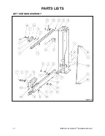
Страница 12: ...PARTS LISTS LEFT SIDE MAIN ASSEMBLY NOVA Dock SentinelTM Installation Manual 12 Figure 15...

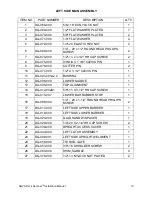
Страница 13: ...1 DG 001 001A2 2 BUSHING 1 12 DG 006 000 LOWER SADDLE 1 13 DG 008 000 TOP ALIGNMENT 1 14 DG 012 002A1 5 8 11 X 3 1 2 HH CAP SCREW 1 15 DG 015 007 LOWER BAR RUBBER STOP 1 16 DG 088 000 1 4 20 x 1 1 2 R...

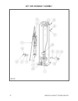
Страница 14: ...LEFT SIDE SECONDARY ASSEMBLY NOVA Dock SentinelTM Installation Manual 14 Figure 16...

Страница 15: ...1 4 DG 035 000 TALL STABILIZER 1 5 DG 038 000 PULLEY GAS SPRING MOUNTING ASSEMBLY 100 GAS SPRING 1 6 DG 049 001 LEFT SIDE UPRIGHT WELDMENT 1 7 DG 064 000 3 8 16 X 1 1 2 HH CAP SCREW 1 8 DG 065 000 3 8...

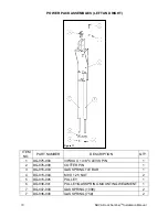
Страница 16: ...ER DESCRIPTION QTY 1 DG 075 000 3 8 DIA X 1 3 8 CLEVIS PIN 1 2 DG 076 000 COTTER PIN 1 3 DG 015 003 GAS SPRING TIE BAR 1 4 DG 015 004 M8 X 1 25 NUT 2 5 DG 015 005 PULLEY 1 6 DG 038 001 PULLEY GAS SPRI...

Страница 17: ...NOTES 17 NOVA Dock SentinelTM Installation Manual This page left intentionally blank...

Страница 18: ...RIGHT SIDE MAIN ASSEMBLY 18 NOVA Dock SentinelTM Installation Manual Figure 18...

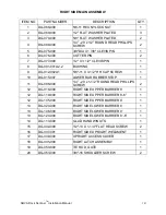
Страница 19: ...20 x 1 1 2 ROUND HEAD PHILLIPS SCREW 2 12 DG 018 000 RIGHT SIDE UPPER BARRIER 8 1 12 DG 119 000 RIGHT SIDE UPPER BARRIER 8 6 1 12 DG 105 000 RIGHT SIDE UPPER BARRIER 9 1 13 DG 020 000 RIGHT SIDE LOWE...

Страница 20: ...RIGHT SIDE SECONDARY ASSEMBLY 20 NOVA Dock SentinelTM Installation Manual Figure 19...

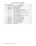
Страница 21: ...ENT 1 6 DG 059 000 PULLEY GAS SPRING MOUNTING ASSEMBLY 8 75 GAS SPRING 1 6 DG 038 000 PULLEY GAS SPRING MOUNTING ASSEMBLY 9 100 GAS SPRING 1 6 DG 038 000 PULLEY GAS SPRING MOUNTING ASSEMBLY 8 6 100 GA...

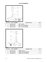
Страница 22: ...000 LEFT LATCH SPRING 1 3 DG 046 000 LEFT LATCH HANDLE 1 ITEM NO PART NUMBER DESCRIPTION QTY 1 DG 041 000 RIGHT LATCH 1 2 DG 046 000 RIGHT LATCH HANDLE 1 3 DG 052 000 RIGHT LATCH SPRING 1 LATCH ASSEM...

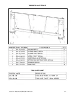
Страница 23: ...OPEN FIRST DECAL 1 5 DG 057 000 CONFIRM CLOSE DECAL 1 6 DG 058 000 OPERATING INSTRUCTIONS DECAL 2 7 DG 100 000 WARNING DECAL 2 8 DG 101 000 SHIM FLAT 12 ANCHORS AND DECALS NOVA Dock SentinelTM Install...

Страница 24: ...must have been properly installed maintained and operated within their intended function and not otherwise abused If your DOCK SENTINEL SAFETY GATE is defective in material or workmanship and you noti...

Отзывы: