Page 8
INERTIA-2464
Technical & Programming Manual
Copyright (c) 1996,
INERTIA FIRE SYSTEMS
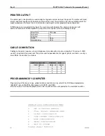
PRINTER OUTPUT
The printer port is designed to be used during testing and commissioning of the panel. The printer will report
alarms and faults together with the date and time of the event, the printer can also be used during walk test
mode to produce a history of the test and can be used to print current programming configuration.
A DB9 plug male is provided at the top of the main termination board. This communication port will
communicate with an IBM compatible serial printer (ASCII printer) with the following settings.
Baud Rate
1200 bps
Data Bits
8
Stop Bits
1
Parity
None
Handshaking
DTR
CABLE CONNECTION
Cabling to the printer requires a 4-core telephone style cable with a maximum length of 10 metres. A DB9
socket is required at the panel end. The printer end is dependent on the type of printer used but is usually a
male DB25. Connection is as follows.
INERTIA-2464 END
PRINTER END
DB9 FEMALE
DB25 M
DB9 M
5
7
5
2
4
8
3
5
7
7
3
3
PROGRAMMING BY COMPUTER
Programming of the zones, relays, global functions and time can by set with the DOS based programme
“2464/SW” only on INERTIA-2464 panels with DATE and TIME.
After the cable is installed the programm can be run and the menu will prompt for the available functions.
Содержание INERTIA-2464/64
Страница 58: ......
Страница 59: ...INERTIA 2464 Technical Programming Manual Page 1 Copyright c 1996 INERTIA FIRE SYSTEMS...
Страница 60: ...Page 2 INERTIA 2464 Technical Programming Manual Copyright c 1996 INERTIA FIRE SYSTEMS...
Страница 61: ...INERTIA 2464 Technical Programming Manual Page 3 Copyright c 1996 INERTIA FIRE SYSTEMS...


