STEP 2. DRILL THE MOUNTING HOLES
Remove the paper backing from the top and bottom of the t emplate. Affix the template to the air duct at the desired
mounting location. Make sure the template lies flat and smooth on the air duct. Center punch hole targets and remove
the template. Drill the holes as indicated on the template. Slide the two speed nuts over the two small holes (Hole A)
next to the sampling tube bushing holes (Hole B) previously drilled in the duct. (See Figure 2.)
STEP 3. MOUNT DUCT HOUSING
Remove the duct housing cover. Slide the foam gaskets over the tube bushings as shown in Figure 2B. Make sure
the two small holes in the gaskets line up with the two base mounting holes. Put one 5/16-inch O-ring over each of
the two #10 sheet metal screws. Use the two sheet metal screws to secure the duct housing to the duct.
CAUTION: Do not overtighten the screws.
HOLE B
HOLE A
DUCT
WALL
SPEED
NUT
SCREW HOLES FOR ATTACHING
DETECTOR HOUSING TO DUCT
FOAM GASKETS
EXHAUST TUBE
(EXTENSION BUSHING)
DUCT DETECTOR
HOUSING
O-RINGS
MOUNTING
SCREWS
INLET SAMPLING
TUBE BUSHING
A78-2046-00
A78-2045-00
Figure 2A. Speed Nut Mounting Location
Figure 2B. Installation of Foam Gaskets Over
Sampling Tube Bushings
TABLE 1. SAMPLING (INLET) TUBES
TUBE
OUTSIDE DUCT WIDTH
ST-1.5
1 to 2 ft.
(0.3 to 0.6 m)
ST-3
2 to 4 ft.
(0.6 to 1.2 m)
ST-5
4 to 8 ft.
(1.2 to 2.4 m)
ST-10
8 to 12 ft.
(2.4 to 3.7 m)
STEP 4. INSTALL THE INLET TUBE
The inlet tube (shown in Figure 3) is identified by a series of air inlet holes on the tube. This tube must be purchased
separately. Order the correct length, as specified in Table 1, for the width of the duct where it will be installed. The
exhaust tube is molded into the base of the duct housing.
The inlet tube is always installed in the right house bushing, with the air inlet holes facing into the air flow. To assure
proper installation, the tube mounting flange is marked with arrows. Mount the inlet tube so that the arrows point into
the air flow. Figure 4 shows the various combinations of tube mounting configurations with respect to air flow.
INLET
TUBE
END
PLUG
AIR HOLES
ARROWS
MUST FACE
INTO AIR FLOW
AIR FLOW DIRECTION
FLANGE
A78-2047-01
Figure 3. Air Duct Detector Inlet Sampling Tube
N500-04-00
10
I56-507-06
N500-04-00
3
I56-507-06
REMOVABLE HEAD COVER
CLEANABLE SCREEN
HEAD COVER
REMOVAL SLOT
VANED CHAMBER
TEST SLOT
P/N RS24 (W/O THERMAL)
A78-1213-01
–Wiring terminal screw tightness
SPECIFICATIONS
Length:
14.5 inches
(36.7 cm.)
Width:
5 inches
(12.7 cm.)
Depth:
4 inches
(10.2 cm.)
Weight:
3.5 lbs.
(1.6 kg.)
Operating Temperature Range: 32
°
to 120
°
F
(0
°
to 49
°
C)
Operating Humidity Range:
10% to 93% Relative Humidity
Duct Air Velocity:
500 – 4000 ft./min. (91.4 – 1219.2 m/min.)
Electrical Ratings for DHX-502A
Refer to the head's electrical ratings.
Accessories
Part No.
Remote LED
RA400ZA
Piezo Alert Sounder
PA400
Replacement Filters
F36-05-00
Magnet
M02-04-00
End Plug For Sampling Tube
P48-21-00
Installation Kit (Parts bag)
A2650-01
Ionization Replacement Screen
RS14
Sensitivity Test Kit
MOD400 or MOD400R
Ionization Cover Removal Tool
CRT400
Remote Test Station
RTS451/RTS451KEY
Programming Specifications/Requirements For Intelligent System Control Panels.
CAUTION:
The CPX-551 and SDX-551 models can be used with the DHX-502 if the following constraints are
observed.
There is a limit to the number of devices per zone that can have their LEDs latched ON. The actual number of devices
is determined by the control panel and its ability to supply LED current. Refer to the AM2020/AFP-1010 Programming
Guide (15530) for details.
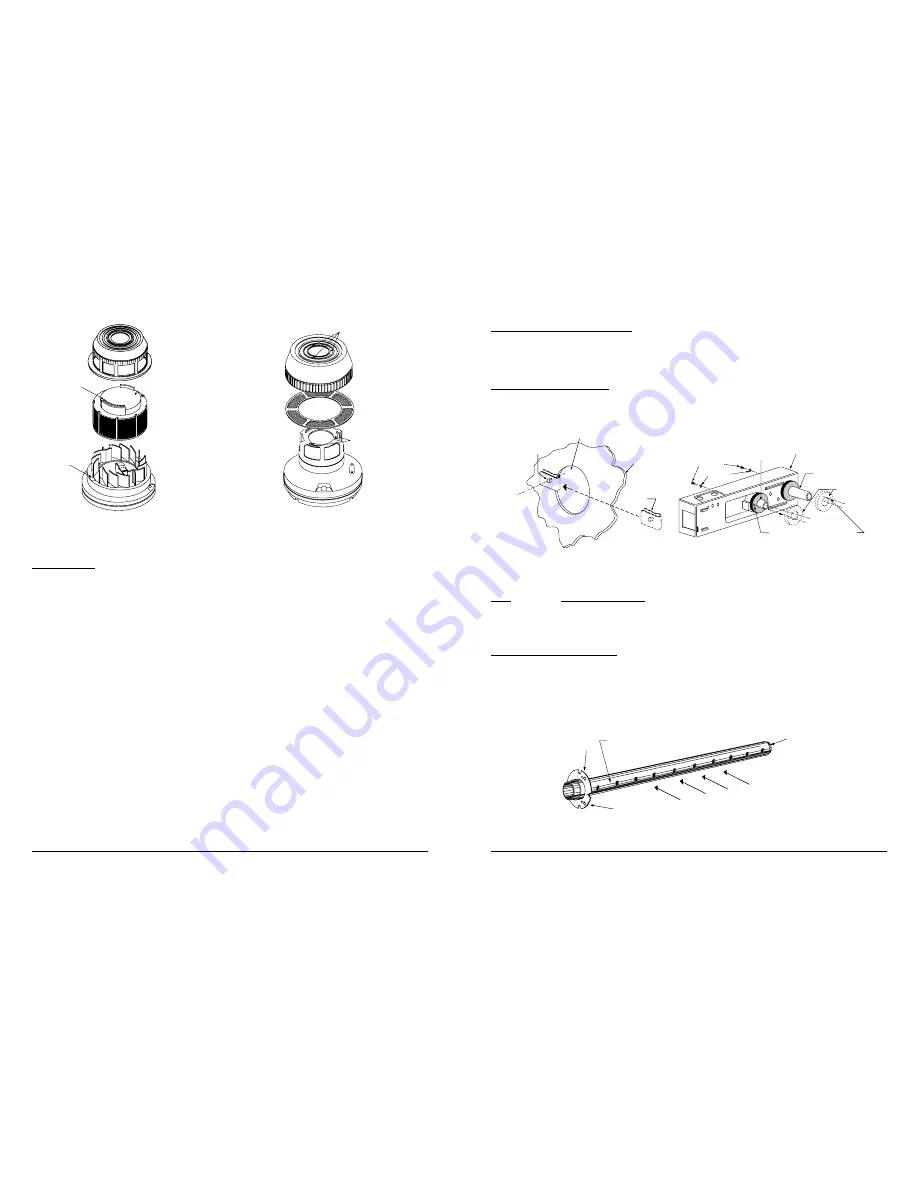
Figure 10. Photo Head Exploded View
HOUSING
LOCK PRONGS
REMOVABLE SCREEN
(P/N RS14)
REMOVABLE
COVER
FOR
CLEANING
HEAD COVER
LOCK PRONGS
A78-1812-07
Figure 11. Ion Head Exploded View


