background image

HAZARDS DEFINED

This manual presents step-by-step instructions that describe the process of installing your NOS Mini 2-Stage Progressive 
Controller. These procedures provide a framework for installation and operation of this kit. Within the instructions, you are 
advised of potential hazards, pitfalls, and problems to avoid. The following examples explain the various hazard levels:

WARNING! Failure to comply with instructions may result in injury or death. CAUTION! Failure to comply with 

instructions may result in damage to equipment. 

NOTE

: This information is important, needs to be emphasized, and is set apart from the rest of the text. 

HINT

: These special instructions provide a handy work tip. 

NITROUS OXIDE INJECTION SYSTEM SAFETY TIPS


WARNINGS 
IT IS NOT LEGAL TO ENGAGE NITROUS OXIDE INJECTION SYSTEMS ON PUBLIC ROADS OR HIGHWAYS. 
NITROUS OXIDE INJECTION SYSTEMS ARE ONLY TO BE ENGAGED DURING SANCTIONED COMPETITION OR 
RACING EVENTS. 

Do not attempt to start the engine if the nitrous has been injected while the engine was not running. Disable the 

lutions 

before attempting to start. Failure to do so can result in extreme engine damage. 

Never permit oil, grease, or any other readily combustible substances to come in contact with bottles, valves, 
solenoids, hoses, and fittings. Oil and certain gases (such as oxygen and nitrous oxide) may combine to produce 
a highly flammable condition. 

Never interchange nitrous and fuel solenoids. Failure to follow these simple instructions can result in extreme 
engine damage and/or personal injury. 

Never drop or violently strike the bottle. Doing so may result in an 
explosive bottle failure.  Never change pressure settings of safety relief 
valve on the nitrous bottle valve.  Increasing the safety relief valve 
pressure settings may create an explosive bottle hazard. 

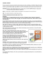
Please note that the NOS bottle label has changed to a two-part 
assembly.  The first label is already located on the bottle.  Upon filling 
your bottle with nitrous oxide, apply the (second) material information 
label in the area indicated in the picture to the right. 

NOTE: The material information decal is located in the same plastic bag 
as the bottle. 

WARNING! Once the nitrous bottle has been filled, it must be shipped 
according to the applicable transportation and shipping regulations! 

Do not deface or remove any markings, which are used for content identification. Nitrous bottle valves should 
always be closed when the system is not being used. 

Notify the supplier of any condition that may have permitted any foreign matter to enter the valve or bottle. Keep 
the valves closed on all empty bottles to prevent accidental contamination. 

fittings. 

It is important that all threads on the valves and solenoids are properly mated. Never force connections that do 
not fit properly. 

Содержание 25973NOS

Страница 1: ...allation improper operation lack of reasonable care or all previously stated reasons resulting from incompatibility with Nitrous Oxide Systems Inc assumes no responsibility or liability for damages incurred by the use of products manufactured or sold by Nitrous Oxide Systems Inc on vehicles used for competition or racing Nitrous Oxide Systems Inc neither recommends nor condones the use of products...

Страница 2: ...rtain gases such as oxygen and nitrous oxide may combine to produce a highly flammable condition Never interchange nitrous and fuel solenoids Failure to follow these simple instructions can result in extreme engine damage and or personal injury Never drop or violently strike the bottle Doing so may result in an explosive bottle failure Never change pressure settings of safety relief valve on the n...

Страница 3: ...2 System Setup TPS Autoset 9 3 3 3 System Setup Stage 1 Stage 2 9 3 3 3 1 Stage 1 Stage 2 Setup 9 3 3 3 2 Stage 1 Stage 2 Graph 11 3 3 3 3 Stage 1 Stage 2 Configuration 11 3 4 Save Load Tune 12 3 5 Controller Setting 13 3 5 1 Touch Calibrate 13 3 5 2 Controller Info Firmware Upgrade 14 3 5 3 Dash Setup 14 Chapter 4 Hand Held Firmware Update 14 Chapter 5 System Operation Testing 15 5 1 Initial Test...

Страница 4: ...tc A progressive 2 stage nitrous system works by pulsing each set of solenoids for a user defined start time cycle time and duration This NOS Mini 2 Stage Progressive Nitrous Controller allows the user to drive the solenoids at different times to tailor power delivery to the engine as needed The user can choose to utilize a window switch RPM a throttle position sensor TPS and or a microswitch to t...

Страница 5: ...a rising or falling voltage The signal type is selected in the software configuration If you are not sure which wire this is consult a factory service manual NOTE CH 1 CH 2 trigger input wires can be used together or separate on the TPS sensor 6 The YELLOW ORANGE re programmable in the software for various purposes such as activating a timing retard etc These have different programmable output tha...

Страница 6: ... of it to prevent shorting out Option 1 Pin Removal Recommended Method Required tools Small flat head screw driver Pin removal tool 567 101 Procedure 1 Use a small screwdriver or other prying tool to gently remove the protective cover from the back of the connector NOTE Be careful not to over extend the tabs on the cover or it will not securely fasten during reinstallation 2 Gently insert 567 101 ...

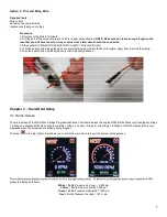
Страница 7: ... the heat shrink a small pull to verify that it is solidly attached Chapter 3 Hand Held Setup 3 1 Home Screen The main screen of the NOS Mini 2 Stage Progressive Nitrous Controller displays the engine RPM Bottle Pressure if equipped Stage 1 Stage 2 activation RPM via colored bars Blue Stage 1 Yellow Stage 2 and Stage 1 Stage 2 ON OFF display ON is only displayed when the solenoids are actively bei...

Страница 8: ...Outlet Coil Pack Systems Note Use this setting to expand the RPM range higher than 9900 For example on a 4 cylinder motorcycle this will allow for a higher maximum RPM window In this mode the control can be set at 3000 and 6000 which will activate at 6000 and 12000 This can only be done if the application is NOT a waste fire ignition system 2 12 cylinder engines when the tach wire is connected to ...

Страница 9: ...noid 3 3 3 1 Stage 1 Stage 2 Setup The setup menu contains the settings which allow you to enable or disable the stage adjust activation and deactivation RPM and enter the Ramp Builder App Enable Disable Stage When a stage is disabled the stage will no longer activate the bar displayed on the RPM gauge will be removed and the menu selections for the stage will also be removed until the stage is re...

Страница 10: ... tailor power delivery to activate when the power can be used most effectively i e delay the nitrous until after launching etc Ramp Time Time in seconds that the ramp builds to the End The more time added here the stage activation will become 0 seconds here will fully activate the stage all at once settings such as start and end will become invalid and not used Stage Duration Time in seconds that ...

Страница 11: ... ramp that has been programmed In reset mode the ramp will start over from the beginning when the trigger has been deactivated and reapplied In resume mode once the trigger is deactivated and reapplied the ramp will return to the last point that the system was active and continue the ramp from that point TPAS Mode Throttle position activation switch mode Changes the type of throttle input Choose f...

Страница 12: ...r you can choose to allow the software to save under the default name Once complete press OK Your tune is now saved to the SD card Downloading Tunes from NOS Visit https www holley com support nitrous_oxide_systems or alternately visit the product page of your specific kit Download desired tune Insert SD card into computer Save desired tune into the TUNES folder found on the SD card If the tunes f...

Страница 13: ...creen 3 5 1 Touch Calibrate If you are having issues with the touch screen not responding or selecting the wrong thing please run the touch calibrate app This will guide you through the process and when successfully complete will calibrate the hand held to more accurately sense the stylus Upload Tune to Controller Delete Tune from SD Card Calibrate the Touch Screen View Controller Info Update firm...

Страница 14: ...then select update firmware If you have more than one firmware update available then you will have to select the latest one 3 5 3 Dash Setup The main screen which displays the RPM gauge and bottle pressure can be changed to suit your vehicles min and max RPM limits If you do not have the optional 15661NOS bottle pressure transducer kit you can disable the bottle pressure display in the dash setup ...

Страница 15: ... to a tach signal input White Red White Blue wires are connected to TPS or a microswitch Large Black wire is connected to a different ground than the small black wire Large Red large Blue wires are connected directly to the solenoids Solenoids are powered via a 12V relay Orange yellow outputs if used are connected to the proper locations Hand held powers up Nitrous parameters have been programmed ...

Страница 16: ...TECHNICAL SUPPORT 1 866 464 6553 NOS Nitrous Oxide Systems Inc All rights reserved Tous Droits Réservés 199R11937 Revision Date 10 17 19 ...

Отзывы: