


80-9369-0120-020 (09-08)
General Product Information
(See illustrations on page 2 for location of switch and valves.)
Function and Operation Sequence
• Selector Mode Switch
• "SC" Speed Control Valve
• "PA" pressure Adjustment Valve
– This is a three (3) position switch that
has positions marked "OFF” “ON” “H/O".
– "ON" position – Unit is in standby, capable of function
activation either by a remote switch or scanner; or by the unit's
integral switch depending upon the Activation Mode.
– "H/O" position – Indefinite hold open. Door will hold open until
power is interrupted.
Power Assist Function Only (PAS).
These units must be manually pushed to the full open position
for this indefinite Hold Open function to operate.
– "OFF" position – All signal inputs are disabled, rendering all
power functions inoperative. The unit functions as a standard
hydraulic door closer.
– Power Assist Function Only.
Adjusts the force required to open the door.
– Power Operator Funtion Only (POR).
Adjusts the opening speed of the door.
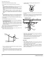
Important:
From closed position to 80 degrees must be 3
seconds or longer and 4 seconds or longer to the
fully open osition.
Factory set adjustment for opening force. Will not generally
require adjustment:
Important:
Power Operator Function Only (POR): The force
required to prevent a door from opening or closing
must not exceed a 15 lbf. (67N) applied 1" (25mm)
from the latch edge of the door at any point in the
opening or closing cycle.
p
VESTIBULE OPERATION
POWER OPERATOR FUNCTION – “POR”
In either Power Operator or Power Assist Function, initiation
of a power cycle may be performed on a delayed basis. This
feature, referred to as Vestibule Operation, allows placement
of the initiating switch at a remote location from the Door
Operator. The adjustable VEST DLY rotary switch/timer pot is
provided for selection a leng h of delay, appropriate for the
particular installation. The basic sequence is shown below:
• Initiate vestibule delay cycle JP1-INV from JP1-OUTV of
another unit or from a switch.
• Set VEST DLY rotary switch/timer pot to delay initiation of
pump motor.
• Upon initiation of pump motor, Power Operator or Power
Assist Function will start.
In the power operator function, initiation of the unit causes
the operator to fully open the door under its own power,
sustain the opened position for a set duration, and then
release and close.
The basic sequence is:
1. Initiate power cycle through any of the following JP1
terminal functions: AUX1, AUX2, RFT, JP1-INV, the L1
limit switch input, the H/O of slide switch or the JP1-O/O
terminal.
2. If JP1-INV is the power cycle initiating signal, read the
VEST DLY rotary switch/timer pot to determine how long
to wait before the power cycle starts.
3. Read the EXSOL DLY rotary switch/timer pot to determine
how long solenoid should be energized or de-energized,
depending upon function required.
4. Read th SW1-2 (A/D) dip switch to determine how long
solenoid should be energized.
5. Read the M DLY rotary switch/timer pot to determine how
long before the pump motor and solenoid valve tu n on.
6. When ELS board reaches upper taught limit, door is fully
open.
7. Pump motor turns off.
8. Read the CL/AS DLY rotary switch/timer pot to determine
the length of temporary hold open.
9. Solenoid valve turns off, releasing door from temporary
hold open.
10. Door closes and operator waits for next power cycle
in tiation.
Additional door open signals received during Step 8 of the Power
Operator function will cause the cl sing de ay timer to be reset to
the beginning.
t
e
r
i
o
l
Exceptions to the Power Operator Function
POWER ASSIST FUNCTION – "PAS”
Following is an explanation of the inputs that can modify the
basic flow of the Power Operator function described above.
1. If terminal JP1-PDET is signaled the door will not open if it
is closed or the door will not close if it is open. This signal
is normally used to connect to a presence detector which
will prevent the door from opening or closing when
someone is in the area of detection. Note that JP1-0/0 will
override the PDET signal.
2. If JP1-0/0 is signaled the door will open independently of
the state of JP1-PDET or JP2-E signals.
3. If the H/0 slide switch is set, the door will open and remain
open. JP1-PDET, JP1-0/0 or JP2-E will override the H/0
signal.
4. If JP2-E is signaled, the power cycle will terminate and the
door will close. JP1-0/0 will override the JP2-E signal.
5. The door must reach its fully open position within 7
seconds after it has started opening or the pump motor
and solenoid valve will be turned off allo ing the door to
close.
6. If the door is in the closed position, and not in the Manual
or Emergency mode, signaling RFT will initiate a door
power cycle. The door will remain open until PH1-RFT is
again signaled or until JP2-E is signaled. If the door is in
the open position, the RFT signal will close the door,
therefore, the door can be "toggled" between an open and
closed position.
In the Power Assist function, initiation of a power cycle
causes the pump motor and solenoid valve to engage,
requiring minimal force to open or close the door. The ease
of operation is sustained for an adjustable duration, after
which the motor and solenoid are turned off, causing the
door to close. If the door is fully opened during the power
cycle, the motor will disengage for the remainder of the
cycle. The solenoid will remain engaged for the duration of
the cycle. The basic flow for the Power Assist mode is the
same as the Power Operator mode except that the 7 second
time-out function is not in effect.
w
6


